Tinkering about with the C. W. Hunt Co.

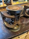
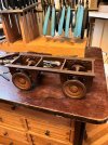
Hi All, Michael Mott introduced me to this site and I have been lurking here for a few weeks. I thought that it was about time to share some work. For the past few years, I have been researching the C W Hunt Co. industrial railway system. The Hunt industrial railways were designed to roll freely around a 12’ radius for use in the tight confines of an industrial setting. With outside flanged wheels and flexible running gear, Hunt rolling stock is a bit quirky and just the sort of thing that I find intriguing.

There are some Hunt catalogs posted on my website at

http://www.narrowgaugechaos.com
Narrow Gauge Chaos - RPC - C W Hunt

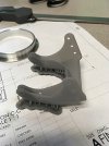
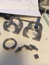
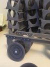
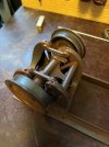
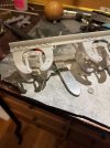
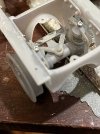
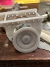
It took awhile but I now have functional running rear in both 1/8th and 1 / 13.714 scales. What follows are photos of the prototype and my models as they evolve.
 

simond

Western Thunderer
Hi All, Michael Mott introduced me to this site and I have been lurking here for a few weeks. I thought that it was about time to share some work. For the past few years, I have been researching the C W Hunt Co. industrial railway system. The Hunt industrial railways were designed to roll freely around a 12’ radius for use in the tight confines of an industrial setting. With outside flanged wheels and flexible running gear, Hunt rolling stock is a bit quirky and just the sort of thing that I find intriguing.

There are some Hunt catalogs posted on my website at

http://www.narrowgaugechaos.com
Narrow Gauge Chaos - RPC - C W Hunt

It took awhile but I now have functional running rear in both 1/8th and 1 / 13.714 scales. What follows are photos of the prototype and my models as they evolve.
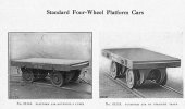
Marty

thanks for that brief diversion over breakfast. A remarkable enterprise!

From my brief reading, I do get the impression that “the solution is big chunks of cast iron, now, what’s the problem?”

cheers
Simon
 

simond

Western Thunderer
Had a chance to read a little more, most interesting - I’d wondered why they reversed the usual flange arrangement, as their approach is far more complicated where pointwork is concerned. It may be that the external flange gives an advantage with the curving performance.

I wondered how the axles steered, and see that the outer wheel runs on its flange, the inner on its tread, but even that poses a challenge as it will only work properly for one radius of curve for a given wheelset, and I guess the flanges wear more than the treads, so it will need some periodic maintenance.

thanks so much for posting that. It must have taken a while to scan, too!
 

michael mott

Western Thunderer
Marty, its great to see you posting about the W C Hunt products. The painted car looks fantastic, I know that it is fully functional or at least all the parts move as they were designed, any chance of a short clip to show that movement?

Michael
 
Hi All,
Thanks for the kind words.
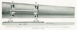
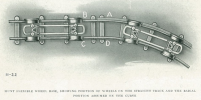
Simond - you are correct about the single radius curve. Hunt standardized the system on a 12' radius. He eliminated sliding friction by making two changes to the standard design of railroad trucks. First, he increased the effective diameter of the outer wheel in a turn. On curves, the outer portion of the car is supported by the flange of the wheel and the inside portion rides on the smaller diameter wheel tread. The inner rail is of standard shape but the outer rail has a surface located just below the top of the rail head for the flange to roll on. You can see the outer surface in figure below. Combined with the track gauge, this difference in effective outer and inner wheel diameter sets the geometry of a cone that freely rolls around a 12 foot radius. To support the increased load, the flanges had a thicker profile than was typical for wheels that size.

Michael - good idea, give me a few days to set up a track.

Regards
Marty

1644637927069.png 1644638173816.png
 

simond

Western Thunderer
Thanks Marty.

your cone diagram explains it nicely. The ratio between the diameters, and their spacing, defines the radius of the curve. I guess a secondary benefit is raising the outside of the wagon slightly, which might stop things falling off! (Youtube has many videos of trucks, cranes and forklifts, whose operators “amusingly” fail to account for inertia)

I still don’t understand why they put the flanges on the outside. This seems to me to make switches/turnouts more complex, as whilst it does avoid the need for checkrails at the crossing/frog, it’s necessary to provide a slot through the stock rail for the flange, and said slot needs to encompass the transition from tread to flange, and straight to curve.

From the pictures of the sleepered turnouts on page 13 it seems that the approach was to make the stockrails join at the frog, and ignore the ramp for the outer wheel until after the blade clearance - I guess it‘s a low speed industrial railway and a bit of imprecision is going to live happily in the tolerances! And it really isn’t any more complicated.

The cast track blades look a bit more involved but given they’ve clearly gone to some lengths to keep the mechanism enclosed, I guess that’s to be expected.

Looking at your other diagram above, it seems the transition from straight (on the tread) to curve (on the flange) was quite abrupt. The straight panels don’t have flange support, the curved ones do. I couldn’t find the dimensions of the wheels but I guess it’s of the order of half to one inch difference, which would be something of a bump when the wheel hits the step. It obviously worked, whatever my misgivings!

cheers
Simon
 
Last edited:
Top