Turned out nice

Martin Shaw

Western Thunderer
Well it' s here.
IMG_0340.JPG
just about 24 hours after it was ordered, which I think is pretty good. Removing the lid and sides of the box, big roll of drums,
IMG_0341.JPG

Of course it's all covered in horrible slimy preservative, which has done its job, but cleaning it off is a muck job. One issue I don't like is the change wheel tooth alignment,
IMG_0342.JPG
the idler gear is some 3mm too far to the right so my 70 year old design Cowells will be needed to make a suitable spacer, and like Ken the change wheels are going metallic toot sweet. I gave it a test run and the motor/ spindle ran well, engaging the lead screw caused a horrible dry bearing scrape, which I tracked doen to the leadscrew pillow block at the other end. Neither of them have oil holes which seems a cheapskate oversight, easily rectified but undoubtedly voiding the warranty. Anyway it all seemd to basically function correctly, so I did what any self respecting engineer would do, and took it to bits.
IMG_0344.JPG
All ready for a massive cleaning tomorrow. There is an interesting financial point to consider here. I paid a smidgeon under £550, and considering the costs and profit for the importer, shipping etc, the factory is making this for something less than say £300. At that price it can't possibly compete with traditional makes like Myford, and why would you expect it to. Having said that apart from a gap bed it will do pretty much anything tha a Myford can, at a fraction of the price, and if properly set up at a perfectly acceptable level of accuracy, at least for my needs. It of course won't last 50 years, but I wont be bothered by then. Well pleased.
Regards
Martin
 

adrian

Flying Squad
Very nice - you might already have found it but Arc Eurotrade publish a few useful photo guides for stripping down and adjusting the lathe and a few other things.

Projects & Articles - Arc Euro Trade

Neither of them have oil holes which seems a cheapskate oversight, easily rectified but undoubtedly voiding the warranty.

The SC3 guide shows a suitable modification for the leadscrew pillow blocks. Photos 101-103.

http://www.arceurotrade.co.uk/machineguides/Super-C3-Mini-Lathe-Dismantling-and-Reassembly-Guide.pdf
 

Martin Shaw

Western Thunderer
Adrian
Thanks muchly for the point, most helpful. I don't quite understand why an oil hole is put in the front rather than the top of the pillow blocks, still I know where my drill is going.
Martin
 

adrian

Flying Squad
Thanks muchly for the point, most helpful. I don't quite understand why an oil hole is put in the front rather than the top of the pillow blocks, still I know where my drill is going.
No problem - glad to help. The only reason I can think of for the positioning of the oil hole is that if they are placed on top then there is a chance that they'll collect swarf from the machining. If you are turning cast iron then you could end up with grinding paste in your bearings. If you are going to place them on top then perhaps a small protective cap would be prudent - maybe the top from a bic pen or similar.
 

Martin Shaw

Western Thunderer
I hadn't thought about that, obviously, and therefore not as good an idea as it first appeared. I wonder if I could get some sprung ball oilers?
Martin
 

Brian McKenzie

Western Thunderer
If you are turning cast iron then you could end up with grinding paste in your bearings. If you are going to place them on top then perhaps a small protective cap would be prudent. . . .

Yes, an excellent thought, Adrian. Working occasionally with cast iron makes a grubby mess of a workshop overtime. Iron dust floats in the air and my painted walls are now a shade or three darker.

I purchased a Taiwanese made machine near twenty years ago. There were oil lubrication holes in the saddle casting - but they were blind holes that lead nowhere :mad:

A former work colleague was mortified when he accidentally drilled into the table surface of a milling machine. I probably didn't help ease his distress by suggesting he stamp 'Oil' alongside the hole :D. A small slug of cast iron was inserted, peened down and dressed off near invisible with a slip-stone.

I wonder if I could get some sprung ball oilers?

I find these difficult to clean thoroughly. There is always a meniscus like tidemark of grit present that can enter when oiling. I use a scriber that has become magnetised to run around the edge of the ball first to attract away as much dirt as possible. On reflection, I don't see any issue with the oil hole entering the side - no different to '0ur' axleboxes in fullsize that retain oil in the base.

-Brian McK.
 

Martin Shaw

Western Thunderer
A great deal of common sense from both Adrian and Brian, thanks guys. I will now do what I was told rather than thinking I knew better. Brian will be pleased to know I have purchased a set of HSS tools which will give me a shape to try grinding my own, yet another learning curve I feel.
Regards
Martin
 

farnetti

Western Thunderer
Well it' s here.

Your last couple of comments are relevant. This lathe would not be suitable if building, say, a 5" gauge locomotive because of the stresses then put upon it but for 7mm (in my case) it works fine with no need for a gap bed. Like you, the first thing I did upon delivery was to strip it down , clean it, and then set it up again using the ArcEuroTrade guide (to the best of my ability). This is now being done again while the new metalwork is fitted.

There are a couple of Workshop Series books dedicated to this lather and, also, if you dig deeper into the EAT website in the links section, there is a site by Frank Hoose which has a wealth of information about upgrades and accessories.

Hope this is helpful.

Ken
 

Martin Shaw

Western Thunderer
Ken
All comments from anyone interested are always helpful, it all helps gain a perspective on what is a major change, if not in my abilities, certainly in the wallet. Also thanks for the pointers to literature, I bought Neill Wyatt's book on the mini lathe back in January when all this seemed a possibility and most helpful it was. I have found the process of stripping down and cleaning useful in understanding how the machine is put together and it also illuminates where the economic corners have been cut. I fear our Chinese friends use a different version of metric measurement to the one I understand, some of the capscrews are dire. None the less I fully expect it will do all I need. Thanks.
Martin
 

phileakins

Western Thunderer
Ken
I fear our Chinese friends use a different version of metric measurement to the one I understand, some of the capscrews are dire.
Martin

Hi Martin

Snap! Those that were present that is. :confused: A lot have now been replaced and after a lot of work I am happy that I have adjusted out most of the backlash and all of the shake in the slides. Now runs as smoothly as the proverbial sewing machine. :)

The Arc pamphlets are very good so far as they go, but there are a number of videos on YouTube which I found very useful when re-fettling my machine (identical to yours by the look of it) and showing how to make some useful mods - adding a cover behind the saddle to prevent chips getting into the gearing for example. Search on 'mini-lathe' to start. Steve Jordan has some good stuff, if you can go with his delivery style, and mini-lathe.com (Frank Hoose's site) is well worth perusing with some good links to videos and improvements.

Phil
 

phileakins

Western Thunderer
Today's little task was to take out the eccentricity in the rotation of the three jaw self centering chuck. It was running nearly 0.2mm off centre line and no amount of bashing with the soft hammer would improve things. Mind you, I felt better! :p

Heart in mouth the backplate was skimmed on its contact surfaces to ensure concentricity, and I found that it was out by about 0.4 mm. Long story short - the chuck is now running at 0.05 mm concentricity, and with minimal bashing applied. That'll do me.

Idly musing over a Sunday night brew - (read beer) - I've now got a chunky lathe but no project to use it on at present unless I take on the 3.5" Conway live steam project, and I really don't feel up to that at present; although the thought of it very attractive.

However, having now got Doug Hewson's G1 wagon book and having followed David Halfpenny's G1 thread ... perhaps a small Manning Wardle to go in front of a wagon or two (1/32 of course)?
 
Last edited:

Brian McKenzie

Western Thunderer
I have no experience with these (small to me) Chinese lathes, but thinking about Phil's need to improve chuck runout, I'd look to see if the following was possible:

Adjust mounting of chuck to backplate - so that the body of the chuck runs absolutely true concentrically and without wobble - and thus without any out-of-balance vibration at higher speeds. Grind a very small amount off the inner end of the chuck jaw that extends closest to the centre line. Repeat until there's no measurable* runout on say a piece of silver steel rod about 3/8" or 10mm in diameter held in the jaws. In really bad cases, it may be necessary to dress off a smaller amount from a second jaw. Then repeat checks to see if any runout remains using the largest diameter material you have to hand.

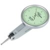
*The purchase of a Dial Test Indicator (d.t.i) is recommended to anyone serious about using their lathe. Tool suppliers commonly offer these in promotional deals, often combined with a magnetic base holder. I prefer finger type to the plunger type and use one extensively for setting up wheels and wheel tyres for modification. Use it also to true up items for milling, finding hole centres etc etc.

-Brian McK.Dial test indicator.jpg
 

phileakins

Western Thunderer
I

*The purchase of a Dial Test Indicator (d.t.i) is recommended to anyone serious about using their lathe. Tool suppliers commonly offer these in promotional deals, often combined with a magnetic base holder. I prefer finger type to the plunger type and use one extensively for setting up wheels and wheel tyres for modification. Use it also to true up items for milling, finding hole centres etc etc.

Adjust mounting of chuck to backplate - so that the body of the chuck runs absolutely true concentrically and without wobble

-Brian McK.View attachment 76818

Yes I have a DTI - plunger type, I haven't found an affordable finger type and the plunger is doing well - and addressing the concenticity of the chuck that is what I've done. The wobble amounts to 5/100 of a mil. What have I done wrong?
 

Brian McKenzie

Western Thunderer
. . addressing the concentricity of the chuck that is what I've done. The wobble amounts to 5/100 of a mil. What have I done wrong?

Nothing. :) :) I took it that you were adjusting the chuck so that work in the jaws ran true (Pratt Burnerd made 'Grip-Tru chucks do this) - rather than truing the body of the chuck as you have done.:thumbs: :oops:

Now with the body running true, have you checked for any run-out of work held in the jaws? If your chuck has multiple sockets for the chuck key (i.e. three, not just one), you may find that tightening at one particular location gives a truer result than at the others.

Cheers,
Brian McK.
 

phileakins

Western Thunderer
Now with the body running true, have you checked for any run-out of work held in the jaws? If your chuck has multiple sockets for the chuck key (i.e. three, not just one), you may find that tightening at one particular location gives a truer result than at the others.

Checking that the workpiece is parallel is the next job on the ever expanding list! Would checking for coning in the turned work be enough Brian or do I need a length of tool steel and my trusty DTI?

Ta for the tip - would never have thought of looking for that. :)

While I'm picking your brains - One job I'll have to do shortly is to check the tailstock as it's one part I haven't taken apart and I really should do. Any tips on what I should do on re-assembly to ensure accuracy with the ways/headstock?

Thanks.

Phil

PS - I chucked a piece of rolled steel rod (scavenged from a printer) with about 4" out, then touched with a tool adjacent to the chuck, setting the cross slide dial. I then touched at the other end - about three thou difference. :eek:
 
Last edited:

Brian McKenzie

Western Thunderer
Phil,

I've never studied the construction of the various Sieg pattern lathes to see what the adjustment possibilities are, but I would caution about being too adventurous. Some of the stuff in Arc's 17 page rebuild document is engineering trade work.

Items affecting parallelism of work (when held solely in the chuck) include alignment of the headstock to the bed. This has a vee shaped groove in the underside, which locks down on a bed V-way, so is a major to adjust - should it be found that the bores for the spindle bearings not be effectively in the same plane.

Unless there is something obviously wrong and is affecting your work, I wouldn't worry too much about alignments. It's not likely to be bothersome for most model parts. That your piece of rod protruding 4" was not quite true could just be a function of the squareness of the chuck jaws at the business end, or slack of the jaws in the body. Try re-chucking your rod several times and see if you get the same readings.

Tailstocks can be troublesome. I've seen two Unimat SL lathes where the tailstocks were so far out-of-whack in manufacture, they were never going to be useful (my own 'SL', now slumbering in retirement, was OK). I suggest cobbling up an arrangement so that your DTI can be held in the 3-jaw chuck, and sweep around the projecting barrel end of the tailstock.

Best thing to do, is start making good use of the lathe and learn its idiosyncracies.

-Brian McK.
 

JimG

Western Thunderer
One job I'll have to do shortly is to check the tailstock as it's one part I haven't taken apart and I really should do. Any tips on what I should do on re-assembly to ensure accuracy with the ways/headstock?

Phil,

A quick and dirty way to check if your tailstock lines up with your headstock is to put centres in the tailstock and the headstock and try to grip something like a six inch rule between the points. If they line up the rule stays square. If there's a discrepancy in alignment, the rule will tend to adopt an angular position which will indicate the alignment error - i.e. the rule angle being in the vertical plane means that your centres have a vertical error; the rule angle being in the horizontal plane means that the centres have a horizontal error. It's also worth doing the test with the tailstock barrel fully in and fully out. You should get the same results at both ends and if you don't it means that the tailstock is either not horizontal or in line with the lathe bed.

From the picture of your lathe, it looks as though the tailstock is one casting so adjustment might be out of the question unless you want to re-machine parts of the casting.

Jim.
 

phileakins

Western Thunderer
Thanks both - advice taken on board.

Actually Jim the tailstock is in two parts as it is capable of being offset for taper turning. I'll try the ruler test, thanks for the tip.

Phil
 
Top