Watermouth - Reviving a vintage P4 layout

stevehowe

Member
I am hoping to present regular updates of progress on restoring our Club's P4 layout 'Watermouth'
Here is a presentation I made for Scalefour North in 2021 which gives some background to the project:

http://scalefournorth.org/wp-content/uploads/2021/03/Watermouth.pdf

The current phase is constructing a long girder bridge carrying the line over an estuary. The model was inspired by the old SR bridge at Barnstaple carrying the
Ilfracombe line over the Taw river
.barnsta[ple bridge 1.jpgbarnstaple bridge 4.jpg
The deck was made from 3,5mm ply, the stanchions are the good old Hornby elevated railway parts, stashed away a long time ago for just such a purpose!
bridge1.jpg

bridge5.jpg
The rails are laid on longitudinal baulks made from 1/8th x 3/16th spruce, the baulk was not quite wide enough to take the Exactoscale checkrail chairs, so a second strip 1/8th x 1/16th was laid alongside. The baulks add considerable longitudinal stiffness to the deck.
bridge8.JPG
The inner rail and checkrail going in.
bridge9.JPGbridge10.jpg
The second baulk and outer rail just starting to be laid.
 

ceejaydee

Western Thunderer
I find the concept of restoring classic layouts fascinating, rather like preserving a locomotive or classic car.
The trouble taken to re-frame a layout whilst retaining the actual baseboard along with the track and scenery is a process to be applauded.
It would appear that in general most layouts are possibly seen to be a transient item with maybe no life beyond a decade if that. For the larger project that may take many years or even a lifetime to complete it makes sense to build with a view to allow life beyond that of the original builder be that natural life or their desire to move on to a new project.
I enjoyed reading the back story of this layout and seeing how you blend the new into the old :)
 

stevehowe

Member
An excellent build of the bridge Steve. Now I know what to do with my old Triang/Hornby piers!

John
The old Hornby/Triang stanchions are actually surprisingly good reproductions, I cut off the clip assembly that fits on the top bearer leaving a low raised section in the centre. This is where it will be attached to the underside of the ply deck leaving a convenient 1mm or so gap either side into which the lower flange of a length of Plastruct I beam can be slotted to form the lower girder. I am planning to try using the Wills sectional plate girder bridge kit to make the actual bridge sides, the length of each section will then determine the final spacing of the stanchions. The bottom plate will be painted to represent slimy concrete, but as there are still a few height issues to be resolved, we may be introducing some packing beneath each one before the stanchions are finally fixed in place.
 

AdeMoore

Western Thunderer
Excellent stuff Steve, looks a wonderful layout and so worthy of time your spending on it.
Agree with all Nick and Christopher say above.
The Taw iron bridge at Barnstaple is a favourite of mine as you can see from my Avitar!
Also a subject of inspiration for my 00 layout currently in build. P4 one day maybe!
So much to model so little time!
 

stevehowe

Member
When the Watermouth baseboards were rebuilt to try and standardise the sizes, we were able to add about 14" to the terminus beyond the bufferstops, this opened up the possibility of creating a bit of streetscape to put the station into some sort of context. There was also a large empty space behind the station building which Pat English clearly intended for something but left no indication of what. The logical answer would be a hotel, owned or at least leased, by the GWR. A search revealed several possible candidates but many were too ‘grand’ or just too big. Fortunately a very old photograph of the original Railway Hotel at Exeter came to light which seemed to have just the right amount of self importance but still remaining within the scope of a relatively modest country town.
1.jpg

Later pictures showed the Hotel to have been greatly extended and the original classical proportions lost. By making some educated guesses I was able to scale off the few images I could find to get a reasonable likeness of the original façade including the very attractive (and challenging!) curved front corner.
2.jpgThe elevations were set out on good quality stiff white card approximately 0.5mm thick which had a slight texture similar to watercolour paper. Once the windows, doors and other features had been drawn up, the card received a coat of shellac to both sides to stabilise it. This is an ages-old method that goes back to the days of Edward Beale and John Ahern. Thin card well shellacked creates a tough waterproof sheet that cuts very cleanly and takes paint well. Much of the rolling stock on Rev. Peter Denny’s Buckingham was built with this stuff. Artist’s shellac is getting difficult to find these days, but a good substitute is knotting sold in any good hardware shop.
3.JPG

Once the shellac had dried for 24 hours, the windows and doors were cut out with a new blade and the outer facades sprayed with Halford’s white primer. I used this because it gave a nice flat finish with a slight texture, and also it is slightly ‘off-white’ so good for representing whitewash.
4.JPG

Windows were always going to be the big feature of this building and there are a lot of them! Club colleague Stephen Grant drew up the artwork to my measurements and had them beautifully etched. They are in three parts; the outer frame and two casements. The favoured colour scheme was to be black and white which always seems to suit these late Georgian, early Victorian buildings. The outer frames were batch sprayed with rattlecan matt black and the sashes matt white primer. The earliest photograph shows the building to have had dark painted windows which was common in Victorian times, but by the 1920’s white paint was becoming increasingly widespread. The parts were assembled with cyno-gel which allowed for a bit of time to adjust, glazing was the plastic covers from Wills plate girder bridge kits of which we have quite a few!
5.JPG
The windows were fixed with Evo-stik which I know to be pretty permanent. The curved windows presented a challenge, but in fact were quite straightforward; I decided to try curving the entire assembly, glazing and all, rather than individual components and ending up with a mis-match. The technique was just the same as for forming locomotive parts; the piece was placed on a pad of resilient foam rubber and rolled with a length of brass bar. Amazingly nothing came adrift and after a few trials, the window frame matched the curve of the wall.
6.JPG

The main facades were backed by a thick card carcass to give strength and this had the window apertures cut over-size to accommodate the outer frames. Not wishing to tempt fate, I decided not to make a backing for the curved section, reasoning that it should be strong enough with the three window frames glued in.

11.JPG
Thats the hard bit done!


6a.JPG
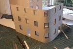
It don’t look so pretty from the rear! (but then, do any of us?) A box-work of painted card strips was built up around each window to create the reveal to the inner wall. Many modellers don’t bother to do this, but it is worth the effort because when glimpsed through the window it adds realistic depth to the building.

Doors and frames were cut from thin card and sprayed matt black, but this looked a bit ‘dead’ so I added a coat of satin varnish to give a bit of relief. The inner lobby was fabricated from thin card painted suitably dull colours and given a quarry tile floor. The glazed inner doors have etched glass panels (pencil behind tracing paper) featuring a classical urn with foliage, thankfully not too visible once the rooms are closed in!
8.JPG
9.JPG
The building to the far left in the original photograph I took to be stables, fortunately it has its back to the viewer! So only the ends and rear wall were modelled. It was connected to the main hotel by a curious little single storey building which appeared to have some sort of decorative pediment. The detail in the photograph is not clear so I concocted a bit of neo-classical architecture to give it some interest. It appears to be a secondary entrance to the main building so I gave it a shallow pitched roof and a long skylight suggesting a glazed passage leading to a separate guest entrance.
10.JPG

Adding curtains, floors and internal walls next!
 

Attachments

  • 7.JPG
    7.JPG
    242.1 KB · Views: 3
Some back-story...

stevehowe

Member
Watermouth is supposedly located somewhere on the South Devon/West Dorset coast. It is likely that Pat English took Weymouth as inspiration for his fictitious terminus. Adding a docks branch to a supposed passenger embarkation terminal, opened up interesting possibilities for additional traffic including Boat Trains.

The map below shows the routes to Watermouth by both GWR and Southern lines.
The location of watermouth in relation to other railways in the area - real and imagined!.jpg
The main route was supposedly built by the Bristol & Exeter Railway from Taunton via Chard originally as Broad Gauge, establishing their foothold on the coast long before the LSWR began extending their system westwards. Although shown as GWR (red), the western route from Axminster was the LSWR's line, although the GWR exercised running powers over it to reach their isolated branchline from Axminster Road to Kilmington. Despite the GWR having the monopoly, the LSWR pressed ahead and constructed their own branch via Axminster with the intention of obtaining running powers over the B & E's timber viaduct across the estuary to Watermouth. The B & E by this time had been absorbed by the GWR and they cited lack of capacity over the single line bridge, thus successfully blocking the LSWR from reaching their terminus and forcing them to construct their own terminus on the north bank of the river. This was then known as Watermouth St. David's. The B & E and later GWR tended to follow a tank engines policy on the branch and so a turntable at Watermouth was not provided, nor was there room for one, causing some problems when the GWR began to introduce larger tender engines to cope with the increasing docks trade. The LSWR had always followed (some would say sensibly) a tender locomotive policy for its route, and so had installed a locomotive servicing point with a 55' turntable close to its station. Following an eventual thaw in relations between the two companies and the reconstruction of the old timber bridge with an iron one, an agreement was reached allowing LSWR (later SR) trains to run into Watermouth Town in return for the GWR's need to use the their MPD with its turntable at Watermouth St. Davids. The station was retained for use by residents living on the north bank and was eventually renamed St. David's Junction in recognition of the dividing point of the two routes.

Schematic diagram of Watermouth+numbers copy.jpg
Schematic diagram of Watermouth terminus. The Docks branch diverged at points 25.
 

Phil O

Western Thunderer
The hotel is still in existence, I used to frequent it for a beer after partaking of retail therapy at the Model Shop, by the Iron Bridge, before catching the train back to Plymouth. Unfortunately, Dave retired and the shop closed down.
 

stevehowe

Member
A quick update as the next phase gets under way. The baseboards for St David's Junction were erected on Friday night for the first time in many years. The new corner board which connects the old baseboards to the bridge section was built some years ago with the benefit of more space it allowed the curve onto the bridge to be eased and provide a site for a locomotive servicing depot and turntable.
file.jpg


The track plan is surprisingly complex!
file.jpg


Modelling archaeology. For some reason Pat English made the point control on these boards manual using wire in tube and rodding and a GEM lever frame. Most of this has failed with age and will be replaced by Cobalt motors, however I felt it should be recorded before demolition.
file.jpg


The platforms are life-expired and will be renewed and the entire area redesigned with LSWR style station buildings.
file.jpg


View from the Down end, the original line followed the siding to the right, the roadbed is in place for the new section.
file.jpg


General view up the line, the entry to the loco depot is the spur to the right.
file.jpg


Awaiting track and final levelling up to the bridge.
file.jpg
 
Top