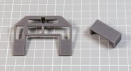
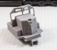
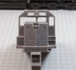
7mm US model dabblings

mickoo

Western Thunderer
I thought this would be easier, especially if they are made relatively generic for the various EMD trucks.
Well the Atlas trucks are not that bad, you proved that with your Dash8, yes you can see the gears between the wheels but I'm kind of wondering if that's such a hate point. They're not OMI brass import quality but you know what, I've got one or two of those models and those trucks can be a bit of an eye sore in some aspects too.

I'm getting to the point that hours expended beyond a certain point is a mathematically diminishing return.

I'm going to try and do something similar with the SD35 flexicoils, thinner wheels, reduced frame width and tweak a few bits here and there, then I'll try and dig the GP35 out as well and have another look at the Blombergs.
 

JasonD

Western Thunderer
Happy New Year all! The Atlas/Roco stuff is all good styrene plastic, except the metal bits. The loco wheels are whitemetal/chrome plated, the annoying freight car wheels are ... yep, styrene, althought they did make token, replacement packs of 4 wheelsets made of metal. The Atlas/Roco drives are nice except for the high pivot centre and somewhere I have some of the replacement, low-mount, metal bolsters produced 20+ years ago. I'll try and dig one out.

Peartree wheels (UK supplier) come in standard UK diameters(!) so 3'1" comes out at 39.7" in 1:48, close enough to 40" diesel wheels for me anyway. Malcolm will do whatever you like in quantity, 100 wheelsets was OK last time I asked. His axles are 3/16" as are Atlas/MTH/etc US producers diesel wheels. I think his normal wheels are UK 'finescale' 0.125" thick probably suit us Nth Am modellers, but if we get some turned specially, we could choose 0.145" NMRA (and 31.75mm track gauge = 1¼", but if you often run on club/your own Peco track...). Anybody want go shares on ... 33/36/40 wheels, maybe with particular types of axle-end: pointed, squared off for roller-bearing caps, etc. I have an order in for InterMountain 33" pointed axles at the moment, they are not in stock currently.
Jason
 

JasonD

Western Thunderer
Yes, I missed out NWSL as a source of wheels for us over here. Delivery schedule news, flexibility and shipping costs have made me do that for the moment, tell me if I'm worrying unnecessarily!
Jason
 

Tim Humphreys ex Mudhen

Western Thunderer
Moving on to the anon, 3D printing and modelling.

I do a lot of it, sometimes it works well, really really well, other times it's a bag of :shit: My biggest problem is that the really well stuff is not my main interest, actually my biggest problem is utter frustration and head banging fests.

To move forward may require a few big steps back if I'm honest, such as 'what the hell are you actually trying to achieve'. I know exactly what I want but am grinding toward the conclusion it isn't achievable, not with the equipment/skill set I current have, so where do you go from there. Anyway, that's a bag of snakes I'll have to deal with later or at some point.

Before I get there some history on where I'm trying to go, there's three possible routes;

1: upgrade RTR.
2: Buy expensive brass.
3: scratch build.

Option one I'm slowly doing with odd models here and there, MTH GEVO, Atlas SD35 plus a huge/growing stash ready for the butchers table.

Option 2 I do as and when I can, ironically it's not the expense that's holding me back, it's the accessibility of the models I really want and even then, expensive as brass is and all the kudos it gets, some models are really not that good under the skin.

Option 3 I've tried, etched Spartan cab and GEVO cabs, they're a step up from most aspects but still insanely hard work and still flawed, I'm not happy with either project to be honest, the 1st Gen EMD cab didn't fair well either, having said that, the MP15DC cab was much better and warrants a further test etch to hopefully bring it to fruition. Even then, the MP15DC is not a totally scratch build, it's an upgrade to a RTR model.

Etches work well for big flat slab sides and surfaces, just doing the spartan nose in etch was hateful, it's square and neat but making all the corner radius uniform and correct was just not good enough.

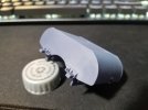
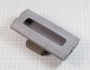
Enter 3D prints, on and off I've been dabbling with a RTR replacement spartan nose for my Atlas Southern Pacific SD35, in my case 2nd Gen 81". This last week it finally hit the home run and works, prints and fits the RTR chassis perfectly.

View attachment 154301

The light grey is from Atlas, medium grey from the hobby printer, dark grey from the Form. The cab front isn't the ideal one I want, although it does fit the SD35 in that they were fitted with extended windows, it's not the L screen that so typifies SP engines back then. I do have a L screen sitting in the queue waiting to be printed.

The sub base doors are not quite right but then there are many other little errors elsewhere (like the massive coupler box that'll need loads of work to put right) so does it really matter, hence my initial repose, 'what the hell are you actually trying to achieve'.

I can keep the bulk of the Atlas cab and just graft on the new front and walk away, in reality that's what I'll probably do with the shell and be done, the rest is another saga for a later day.

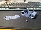
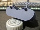
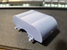
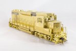
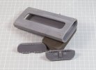
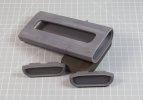
Buoyed by that small success I decided to try something more adventurous. I've not cleaned it up as there are bits still with errors in and some own goals, like forgetting to turn on the tread plate layer when exporting the chassis, pah :headbang:

View attachment 154302

View attachment 154303


View attachment 154304

View attachment 154305


This is where 3D prints are really :shit: making one to fit a known location is hard work, but possible, making six all work and fit together is a hate fest, each part is just ever so slightly out it makes joining them all up with out gaps a nightmare.

The cab floor was an own goal, it clearly all fits in CAD but the swelling, flexing of the print in the machine of co-joining parts means it doesn't bloody well fit, not a little, a lot, so it needs re doing and compensating to get a better fit.

The same goes for the sub base cabinets, even with sacrificial edges to help joints there's still a small flex or bow in the base, about 0.3 mm between ends and centre, you can sand if flat but the bow works it's way up the side until it eventually fades out. That means that the lower rib on the longer door is also bowed slightly, thus even when you sand the base flat, that detail remains bowed.

The cab front....with signature SP L screen needs a different orientation to move the sacrificial edge away from the window frames, near impossible as they're an opening so at some point, an edge some where is going to be a sacrificial edge, that's the nature of SLA printing, the art is to minimise it as best you can, which on that point I might have an idea brewing.

The chassis, or that which is part of the body shell is ironically near perfect, except some berk forgot to turn on the tread plate layer when exporting, quite an expensive error given it's mass and time loss to print it (15 hours).

All in all, not the utopia I was hoping for and it'll take a lot of further testing, tweaking, printing to progress further/better, to the point where one has to ask is it worth it and yet once again, 'what the hell are you trying to achieve'. More importantly, this might not be the best way to do it.

Given the benefits/failures twixt etch and print, each has it's place, mixing them in this instance may also not be the right way forward either, what I can say though is that printing is a significantly faster process, etching can take days/weeks to draw up and then up to six weeks for delivery, then goodness knows how long to build.

I need more beer :))

Hi Mick,

Probably a daft question but here goes, could you print the whole cab as a single unit rather than as separate components?

atb
Tim
 

Yorkshire Dave

Western Thunderer
Well the Atlas trucks are not that bad, you proved that with your Dash8, yes you can see the gears between the wheels but I'm kind of wondering if that's such a hate point.

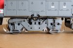
Not really, by the time the missing detail is added the gears start to disappear and you would only see them at eye-level under close scrutiny. I'm not really bothered as long as the drive truck does what it's supposed to do :). This is on my Dash 8.

Truck 02.jpg

The Atlas Blomberg hides most of the drive gears anyway and by the time detail is added - especially the underframe :eek: - they'll almost disappear.
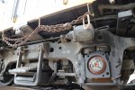
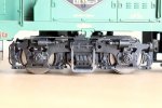
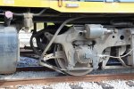
The biggest detail on these trucks (or lack of) which shouts out are the journal springs - where are they? and the brake pull rods compared with the GP9 below (which you kindly produced etched versions some time ago).

Truck 01.jpg

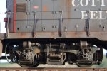
And I think the Roco Blomberg truck frame is a far superior moulding even though it dates from the 1970's. A bit of work is required on the Atlas Blomberg truck sideframes to bring them up to this level. :cool:

Truck 3.jpg
 

mickoo

Western Thunderer
Dave, yeah those Roco trucks are rather good, maybe to the point of just bagging really cheap broken models off Ebay and salvaging the side frames for Atlas models.

I don't mind the drive train either to be honest and I always only plan to drive the rear truck on my US models, I don't have the space to run scale length trains so no need for the extra traction. That does then allow for clear cab models which are a more important aspect than pulling power.

I'd not noticed the lack of primary springs on the Atlas Blombergs before :eek: and their spring hanger plank safety strap could do with a little bit of beefing up, the direct comparison with the Roco one shows that up really well.
 

mickoo

Western Thunderer
Hi Mick,

Probably a daft question but here goes, could you print the whole cab as a single unit rather than as separate components?

atb
Tim
Tim,

Not as daft as you might think, but no where as easy as one might imagine either.

There's a couple of initial points to consider off the bat, not every print is perfect, most have a small error here or there, the trick is to try and foresee that and aim for it to appear in an area that's not visual. The bigger the object, the higher the risk of the error appearing, sometimes several times, thus the higher risk of the part failing. Given that resin is expensive and the time taken to do a full print might be 20-30 hours, that's a high risk gambit. You can design your model to significantly reduce the risk of errors and that's where I'm at with the sub components, each in it's own right is not too far off the mark, but combining them will need redesign and more testing/failure.

The second and more important factor is your support faces (sacrificial) and cleaning up there of, there's also the factor that surface detail prints really well in one axis but often not so well in others, that's the nature of the machine and the process.

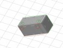
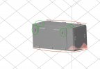
If you print flat (a simple battery box test piece, forgive the rendering from the slicer, it's not the most detailed) then we have thus.

Image.jpg


The edges in green will be nice and straight, the sacrificial edge will be the base and easily sanded smooth but the details in red will be ill defined. If you have to print like this then the details need exaggerating by about 25-30%.

Tilting the object increases the detail definition but then runs the risk of layering (steps) from the print process, there are angles which are really bad and there are angles where it's almost impossible to see and easily dressed out. The form is a laser (pure digital printing) so layering is more pronounced, other printers that use LED screens can blur edges or add anti-aliasing to smooth the effect (sort of a semi analogue print)....but it also rounds off details, you have to decide which way you want the trade off to go.

Image2.jpg

Once we have tilted it we then run into extra issues, the base facing the build plate now runs the risk of bowing due to the peeling nature of SLA printers, the bowing on the Form is only for the first few mm so you could add a skirt to that area and them trim it back in post processing. Angling also makes the top details much better but the side ones are still not optimized.

More importantly our sacrificial support edge is not only on the base, the rear face has angled and is now facing the build plate and runs the risk of puddling, requiring supports, cleaning up; all of which now precludes that face of having any detailed surface detail.

To gain optimum surface detail on the battery box side we need to tilt in another axis.

Image3.jpg

Now our surface detail is optimized but we now run the risk of bowing on several edges, our sacrificial support edge now is on three faces, the base, the rear and the inner edge.

Lets now imagine my battery box has details on the rear and inner faces, as it would if it were a complete nose end and cab, where do you put your sacrificial edge, bearing in mind now that you have many faces all with surface detail that you want to retain and not add supports to.

Conversely, if I were printing middle earth Dwarves, Trolls, Elves and Orcs then 3D printing is superb, they all have rounded edges and humane shapes, those sorts of items are the bread and butter of SLA printers; engineering shapes are not so easy to replicate, not to me anyway :D

There is an option to mix media, you could print the sub base units as blanks lets say, then add etched overlays, been there, done that, got the T shirt, not as easy an option as one might think. Problem one is finding a decent adhesive to stick the two together, in time most of mine have dropped off.

The second issue is with the etches, to get surface detail like that it has to be half etched, that results in the panels being slightly curled and I've yet to find a way to effectively flatten them without distortion damage.

Img_3512.jpg

I've got a revised cab front in the printer now, hopefully my new sacrificial edge theory will work which means three out of the five sub parts are now acceptable for reliable printing.
 
Last edited:

Big Train James

Western Thunderer
In defense of the Atlas truck, the springs, or lack thereof, are actually a fairly accurate rendition of some of the prototype variety. There are spring seats, I presume earlier versions, that cover nearly the entire spring.

Copyright to Mike Danneman as noted on the photo:
6997.1395767313.jpg

If I had to guess, I say that the earlier version is a cast part, while the more modern versions are stampings or welded fabrications?

I'd also say that the Roco version shows a bit too much spring. I've never seen an open spring on a locomotive, usually the sideframe sits down quite far on the journal, at most I'd expect to see about 1½ turns of the spring or just the beginning of the second turn.

Copyright to Greg Grice as noted:
4089.1471401308.jpg

The Atlas sideframe isn't bad overall, but it does suffer from the usual depth and undercut compromises like any other molded part. Plus everything in the area of the journals seems pretty anemic to me.
 

mickoo

Western Thunderer
Well there y'all go, every day is a school day :thumbs:

I checked my own photos and they show the same, I should also refrain from shooting from the hip as one can have a tendency to shoot ones own foot :))

Img_1940.jpg

Img_3444.jpg

The swing hanger bracket is actually more realistic on the Atlas truck, the tie bar is really that thin, though it could do with being moved up a bit and maybe the bearings beefed up a little more, an ideal 3d replacement part.

I know there are several variations of Blomberg, so the Roco one might fit those better, I've not looked yet, too busy redoing all my tread plates in CAD, who'd think EMD would change them along the way ehh :rolleyes:
 

Big Train James

Western Thunderer
Just getting started with the 3d printing here, about a month in with a new Mars 3. I'm sorting through all of the issues that Mick has been discussing in his last handful of posts. I will say that it can be quite rewarding, and empowering, to have your own printer. It can also be quite maddening as Mick suggests. I'm absolutely blown away by the quality of some of the items I've printed. But I'm frustrated by what can seem like a moving target as I try to learn and build experience toward having confidence that the file I input into the printer will ultimately yield a successful part.

One thing I knew when I started, is that just because you could print an assembly all at once, it in no way means that you should. Something like a complete cab or a fuel tank with all the details added, will almost certainly turn out better done as constituent parts rather than as a whole. The following is the fuel tank for my sw1500 project. I've split the tank apart into a carcass and the two end sheets, plus any of the add on details like the piping, fuel fillers, float gauge, and sight glass gauges.

emd fuel tank.jpgemd fuel tank 004.jpgemd fuel tank 002.jpgemd fuel tank 003.jpg

By doing the end sheets as separate parts, I could avoid orientation and support issues where supports would have marred the finished surfaces of the tank. With integral end sheets, I would have had to place supports on either one of the end sheets, or on the scalloped tank body itself. The end sheet would have been fairly simple to clean up with sanding. The tank body though features the facets that are a product of the press brake forming process. It would have been difficult and tedious to clean up that surface without softening the detailing.

By doing the small details as individual pieces, I could avoid undercuts and situations where support might span from one finished surface of the model to another finished surface. It also left large flat surfaces that were easy to sand without having to work around the details. The other benefit is that, if printed integrally, I would be guaranteed to break off any protruding details like the fuel fillers, while working on the tank body. As separate parts, they can safely be added after the rough work is finished.
 
Last edited:

Dangerous Davies

Western Thunderer
Just stumbled upon this thread and I wonder whether anyone could shed a little light on an O gauge GP30/GP35 that I picked up as a non-runner and am slowly sorting out.

It has a flared out section mid way along the bonnet (hood?) so this makes me wonder if it is more likely a GP30. The bogie centres scale out at 35 feet which is correct for a GP35, did the GP30 have the same centres?

It has die cast Blomberg trucks by Atwater which have all axles driven via transfer boxes and cardan shafts from a centrally mounted motor which looks like something out of Faraday's lab.
The body is constructed from brass and it has Santa Fe livery with the running number 3312. This could be entirely fictitious of course. I have heard that Red Caboose made brass body kits, possibly it is one of theirs.

Does anyone know if spares are available for the Atwater trucks ie wheel bearings or has this firm long gone?

Thanks and apologies for hi-jacking the thread.

Dave
 

mickoo

Western Thunderer
GP30 and GP35 variants are dead easy to tell apart, one of the easiest in the EMD range I'd say. Both engines have virtually the same chassis so truck centres and distance between pilots will be the same, maybe a few inches difference in the pilot to pilot length, I'd have to check the drawings to be sure but fundamentally they're the same.

The flared mid section is the dynamic brake section, common to a lot of EMD engines but an option for Railroads, those Railroads mainly based in flat lands don't have this fan and flared blister fitted.

Your easiest spotting differences between the two is the cab roof, the GP35 has the standard Spartan cab profile (angular) that went on to spawn thousands of other engines, the GP30 is unique in that the dynamic brake section extended forward over the electrical cubicle and onto the roof. The cab roof is also rounded at the cant rail, a carry over from Gen 1 engines with their fully curved roofs, GP9, SD9 etc but a different profile.

This is an OMI GP30 which shows the raised roof section, although this model has the dynamic blister sheet metal work, it's not actually fitted with dynamic brakes, those grills and fans have been removed (and I now need to add them back) . The grills you can see are for the electrical cabinet and engine intake.

IMG_0607.jpg

Never heard of Atwater so can't really help there I'm afraid.
 

simond

Western Thunderer
there’s an article in this month’s 0 scale resource about making lost-wax cast 2- and 3- axle trucks Using 3D printed masters & inserts.

I think this link will work


mickoo

Western Thunderer
Fuel tanks have their own special form of hate, it's a simple shape so should be easy to replicate, my mileage tells me different.

Part of that is poor CAD design, part of it is inherent to SLA print technology.

I did several test runs on a SD75I fuel tank, considerably bigger than Jim's and that in it's self present some issues. You can't print it as one as nearly every face needs to be good, there are no natural sacrificial faces or areas so it has to be broken down.

My tank is slightly different than Jim's, in that the end sheet is inset into the wrapper skin, earlier tanks like Jim's have the end plate on the outer end of the wrapper skin, that makes for an easier (relative) joint/mating surface.

I didn't bother with fixing plates like Jim nor internal structures/supports (neat idea that) or the bending break lines, I'd worry abut that detail once the basic shape could be replicated reasonably consistently.

The main core is long and can only really be orientated near vertical, probably it's optimum angle anyway, but I've found and bits that stick out tend to deform, the two small square tabs are not perfectly square, they've become rounded due to the peel process and high angle of orientation.

The problem with big long sections is that they tend not to be wholly accurate along their full length, therefore the profile at the base can be slightly different to that at the top end, however the top end will be nice and flat and the base (sacrificial face) can be sanded smooth. In reality the best orientation would be purely vertical, but then your only making a plastic tube and you might as well roll some brass sheet and replicate the same.

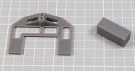
These are the constituent parts.

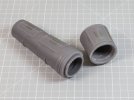
IMG_0701.jpg

Lovely detail on the end plates and the tank core is reasonably flat and smooth, but if you eye it up at tighter angles you can see slight deformations along the length, maybe they would go with internal supports, my gut feeling it that internal supports will at some point have a big change in surface area and that will leave a ripple on the outer surface. Large changes in layer surface area are a big no no and should be avoided where possible, hence angling prints etc.

On the rear we run into the poor design of the end pieces.

IMG_0702.jpg

I have made a rebate in the tank core and then a raised edge on the tank ends, the problem is this raised section is part of the sacrificial area, the part where the supports are and where resin puddles, whilst I can clean the support face, I cannot clean the rebate it makes with the end piece, that area has a lot of puddled resin and is rather quite blobby.

When you fit the ends into the core you end up with an ugly gap to fill.

IMG_0703.jpg

The left hand end isn't so bad but the near end is dreadful, you can see the lumpy surface caused by the supports and resin puddling.

One way around this would be to split the tank 50/50 and have just one joint in the middle but that will run the risk of the two ends not being perfectly formed and match exactly. The other option is to do something like the Garratt bunker and have two flat surfaces, then print a plug to join the two.

IMG_0705.jpg

The plug/ring is fitted to the larger tail end, it wasn't printed like this but pushed into a rebate similar to the one on the short front end. The bunker is an easier option because it has a natural break where the roller rings are, therefore you can get a neat tight joint and no cleaning up is necessary.

The problem with applying the bunker theory with the fuel tank is that you will still end up with a joint near to each end that will need filling and dressing smooth..

I'm going to have a similar problem with the EMD chassis as it'll need to be four sections and getting seamless joints in large resin parts can be problematical, not impossible, but mentally challenging to design and implement.

The natural conclusion I came to with big fuel tanks is that 3D printing is perhaps not the best medium, small tanks like the GP9, SW1500, MP15 etc then yes it has merit worth exploring further, but big modern tanks may be a volume too far.
 

mickoo

Western Thunderer
there’s an article in this month’s 0 scale resource about making lost-wax cast 2- and 3- axle trucks Using 3D printed masters & inserts.

I think this link will work

Yes I skim read that the other week, I'll go back at some point and read it in detail, always good to see how others approach common problems.
 

Dangerous Davies

Western Thunderer
Mick
Thanks for your prompt response and the photo of your GP30. Very nice it looks too! As you have pointed out the cab is a big giveaway. Mine is definitely a GP35 as it has the angular cab with nothing above it.

Cheers
Dave
 

mickoo

Western Thunderer
Okay, I think I'm going to have to accept that this is about as good as I can get with the cab front, it's free from warps, square and has thin window frames, currently 0.60 mm if you include the rubber seal. I could probably push that down to 0.35 mm but run the risk of the thin edge getting the crinkles, especially when cleaning in IPA which softens it even more.

Compared with the Atlas 2.3 mm thick (including rubber gasket) window frames it's an improvement, compared with etched brass at say 0.35/0.4 mm then it's not quite there.

There's a little wavering of a couple of window frame edges but you have to look hard to see it and once glazed, painted and weathered it'll hopefully not be that obvious.

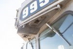
The optimum orientation required one support to the small triangular panels beneath the number boards, I suspect many people do not know they there, I didn't until I crawled over 9950 at Barstow a few years ago.

IMG_4561.jpg

The orientation like the battery box means that this panel will need to be exaggerated to show better but the support (LH side window) comes from the rubber gasket on the L screen, I've left the pip there so y'all can see where it goes.

The upshot is that these two panels will be removed and I'll add them as thin small etched items later.

The front view and top of battery box test 3.

IMG_0706.jpg

The rear view (note to self, clean off prep work dust before taking photos) and battery box side.

IMG_0707.jpg

Fitted to nose section, still needs a little work on the base where it meets the sub base panels, but both these and the noise need further reworks which should solve that.

IMG_0708.jpg

Head on shot showing the classic SP L screen package.

IMG_0709.jpg

The battery box details are getting there, I need to tweak some aspects to try and get some better definition, but again, I think it's close to where further improvement will not materialise unless I can think of anther way to get it better. Orientation and sacrificial edges are about as good as they'll realistically get.

Adding paint will naturally dumb some of these details down, so I might have to have to make further changes once I get to that point.
 

Overseer

Western Thunderer
Just stumbled upon this thread and I wonder whether anyone could shed a little light on an O gauge GP30/GP35 that I picked up as a non-runner and am slowly sorting out.

It has a flared out section mid way along the bonnet (hood?) so this makes me wonder if it is more likely a GP30. The bogie centres scale out at 35 feet which is correct for a GP35, did the GP30 have the same centres?

It has die cast Blomberg trucks by Atwater which have all axles driven via transfer boxes and cardan shafts from a centrally mounted motor which looks like something out of Faraday's lab.
The body is constructed from brass and it has Santa Fe livery with the running number 3312. This could be entirely fictitious of course. I have heard that Red Caboose made brass body kits, possibly it is one of theirs.

Does anyone know if spares are available for the Atwater trucks ie wheel bearings or has this firm long gone?

Thanks and apologies for hi-jacking the thread.

Dave
Without seeing the model or knowing when it was made it is hard to know which model it is intended to be. The 35' bogie centres don't match a GP35, they have 32' truck centres, as do the GP30. The GP38 has 34' truck centres, as do the GP40 as far as I know.
 

Big Train James

Western Thunderer
When you fit the ends into the core you end up with an ugly gap to fill.
Presuming I'm understanding the pictures correctly, I'm wondering why you aren't making the tank core the full length, and making the end piece sit down inside the tank core, rather than having the end of the tank core combined with the tank end sheet? By combining the end of the core with the end sheet, you get that joint and gap in the surface of the core, that is meant to represent a continuous piece. By making the end sheet smaller and setting it inside the end of the core, it makes the joint between surfaces at the logical point where surfaces are perpendicular to each other. The mounting brackets could still be printed as part of the end sheet, with proper allowance to clear and wrap up and around the end of the core. I fully understand that it may take several iterations to get the fit of the two parts just right, but it can of course be done. One thing I did was print only a small length of fuel tank, just the end with the end sheet mounting pin locations, so that I didn't waste time or resin doing the full tank.

The end of the tank core would need to have a thin edge to represent the end of the sheet, but it will be a very small amount, and if doubled to roughly ¾" prototype wall thickness, will meet or exceed the .3mm model wall thickness that seems to be a good standard minimum.
 
Top