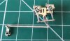
Finney 7 LNER A4

P A D

Western Thunderer
Pete,
It looks to me to be an inset panel - in which case scribing its outline will look better than an applied piece. I'll be interested to see how you get hold of bolt heads that small though!

Interesting to note that the section of the panel looks to be perfectly rectangular from underneath; is that how the secondary buffer springs are removed, I wonder?

Steph
You're right Steph. Maybe not so easy to do after all particularly as it is curving in 2 planes. I checked my Acme A4 and I did not put them on after all, but I do remember considering it.

The blog states quite clearly that it is an access panel to Jack the locomotive up by the buffers. The red stands are not supporting the engine on the buffers but on the main frames where the original guard irons were fitted.

Duuuurgh! Note to self - read the caption.


Cheers,
Peter
 

P A D

Western Thunderer
Moving on to the valve gear here are the the expansion links and radius rods being assembled. The expansion link is made from 4 parts pinned with 0.5mm rod and soldered. 20181217_162516.jpg

The radius rod is assembled around the inner two laminates and then the outer laminates are added. Here they are before the outer faces were added to the expansion link.
20181217_162443.jpg

And completed.
20181217_162352.jpg

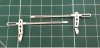
Here the pivots for the expansion link are being prepared in the motion bracket. First short lengths of rod are soldered in place, trimmed and cleaned up.
20181217_175106.jpg

Clamped in the vice , I then made two cuts with the piercing saw to remove the centre portion, to leave a "stud" either side for the expansion link to pivot on.
20181217_175656.jpg
Here the one on the right has been sprung into place. The other one shows the washers soldered either side of the link to take up the slack and keep it centred in the bracket.
20181217_182517.jpg

Next the two to one levers and front valve rods were made up.
20181217_195956.jpg

And trial fit in the valve guides.
20181217_202244.jpg
The 12 BA bolt is just placed through the holes to line it up.
20181217_202257.jpg

Here are a couple of views from each side showing it all in place. 20181217_202321.jpg

20181217_202341.jpg

And with the body on. I'm pleased to say the return crank lines up nicely with the union link, no bending will be required, which spoils the look of the gear.

20181217_213531.jpg

Finally, as it won't have a speedo fitted, I swapped the 12 BA steel nut for a cast NS one from Laurie Griffin and trimmed the excess bolt on the left rear driver.
20181217_203249.jpg

Cheers,
Peter
 

P A D

Western Thunderer
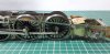
The valve gear is mostly complete now appart from a few remaining pieces and some tidying up here and there. The kit provides an etch part on the N/S fret for the gap at the end of the slide bars, but it should be brass so I'll replace it. The overlay for the bearing on the return crank is still to be added, and I'll do that with epoxy.

20181218_182401.jpg

All joints are pinned with lengths of N/S rod soldered on the back of the forks only. Must be improving as I didn't manage to solder any of the joints solid this time. I'll need to suss out what lubricator piping is needed otherwise the A3 will show it up.
20181218_182340.jpg

For the moment the link between the front and rear valve rods is a length of cable insulation. I'm considering leaving that on as it works OK and on the A4 can always be got at later if needs be.
20181218_182439.jpg

The cylinders and valve gear are demountable which is a benefit when painting. I'll take it off and take some photos when it's done.

Here's a view with he body on.
20181218_182313.jpg

And t'other side.
20181218_182054.jpg

And with the tender. The other benefit of the resin casting is that it stays clean, unlike the brass, which tarnishes if you look at it.
20181218_181723.jpg

Some closer views of the valve gear.
20181218_181928.jpg

I still need to fit the Laurie Griffin castle nuts to the coupling rod joints.

20181218_182021.jpg

20181218_212421.jpg

Looks the part and aas quite straight forward. I hope the 2mm valve gear (lubricator linkages) go together as easily.

20181218_211918.jpg

20181218_212040.jpg

Cheers,
Peter
 

Genghis

Western Thunderer
The lubricator linkages are a lot of fun (!). I was only pleased that it was the 7mm kit I built not the 4mm! They look the part when complete though.
Excellent work as always.
Dave
 

P A D

Western Thunderer
The valve gear is all done and dusted.
20181219_185142.jpg

I decided to go with a "U" shaped piece of wire to link the valve rods. The slide bar extension inside the cylinders supports the wire when soldering. A drop of oil is needed to allow smooth running.
20181219_185112.jpg

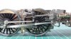
Back on the chassis set in mid gear. The return crank bearing cover has also been fitted.
20181219_184903.jpg

Reverse gear.20181219_184936.jpg

Forward gear.
20181219_185041.jpg

The reversing lever is fixed with a length of wire at the rear, soldered into a hole in the rear frame and to a bracket on the main frame about mid way. At the front you can pin it to the arm on the lifting link, but only in mid gear. At the moment the pin is soldered to the reversing lever but loose in the arm. I'll decide what to do on that later.
20181219_184651.jpg


Here are some views with the body on. Leaving the reversing lever loose at the front is not really an option as it is very thin and easily bent.20181219_183948.jpg

The slide bar ends have now been closed with a length of 1mm square brass rod.
20181219_184020.jpg

T'other side.
20181219_184051.jpg
The bearing cover on the return crank was carefully glued in place with epoxy so as not to gum up the works.
20181219_183851.jpg


I think the daylight seen above the valve guide is due to the gap in the frames for dropping the cylinders in. I'll see if I can fill that with a strip of waste etch soldered to the cylinder stretcher either side.
20181218_212421.jpg

No daylight this side but the angle is different.
20181219_183819.jpg

They don't show much being hid behind the frames at the rear, but I must get some injectors from Ragstone. I'm not sure if the kit caters for the cod's mouth winding mechanism visible on the frames in front of the valve guide, but if not I'll knock something up.
20181219_184616.jpg

Which makes me wonder if the winding mech was on both sides? Need to check.
20181219_184200.jpg

Cheers,
Peter
 
Last edited:

P A D

Western Thunderer
Many thanks Bob.

So two sets of winding gear to make and the bogie side checks. I'm having to do more scratch building than Nick Dunhill on his NG G16! These Finney Kits are not all they are cracked up to be. :);)

OK, they most definitely are.

Cheers,
Peter

PS. Wonder if the above were on the W1?
 

P A D

Western Thunderer
So on to the lubricators and linkages.
I've plagarised Nick Dunhill's technique for rounding of the etched hand wheels. First they were soldered to a short length of rod, to allow turning in the drill and rounding off the cusp with a file and emery. To finish off I rub the outer faces on a nail buffer. Here's a before and after view 20181220_115006.jpg

And after polishing on the nail buffer.
20181220_144744.jpg

Here the lubricators have been mounted on the bracket and the links fitted to the rear one. The remaining link is to the right and as can be seen upper left, there are spare links in case you screw up.
20181221_083837.jpg

And with the front link added.
20181221_092551.jpg

Here is the return crank and eccentric rod. The rod is half etched and very thin so I decided to beef it up with some spare half etch strip.
20181221_185849.jpg

The joints are pinned with 0.6mm NS rod soldered on the rear faces only.
20181221_202233.jpg

Here's the real thing on Bittern.
DSCF0041.JPG

And here the return crank/eccentric joint.
DSCF0042.JPG
And my interpretation on the model.
20181221_205932.jpg

20181221_192131.jpg

The tops of the lubricator castings needed some filing and polishing to get them smooth.
20181221_151825.jpg

And with the body on. The apertures in the running plate needed a little filing to clear the lubricators, but nothing much.


20181221_191942.jpg

I made a start on the draw bar but ran out of time, so some rounding of the rear end is still to be done. I should have soldered a 6BA nut on the running plate under the footplate, but muppet that I am, I overlooked it. To get around that a nut had been soldered to the underside of the rear spacer. The draw bar has been laminated from 3 strips of waste etch rather than use the flimsy etchings supplied.

20181221_190220.jpg

And a final shot with the tender
20181221_190049.jpg

Cheers ,
Peter
 
Last edited:

Genghis

Western Thunderer
I'm looking forward to the video: the valve gear and lubricator drive in motion is quite hypnotic.
 
Top