You are using an out of date browser. It may not display this or other websites correctly.
You should upgrade or use an alternative browser.
You should upgrade or use an alternative browser.
7mm 7mm Mick's Workbench - JLTRT Royal Scot
- Thread starter 7mmMick
- Start date
7mmMick
Western Thunderer
LNER buffers, Markits or Slaters perhaps?
Cheers
Tony
Cheers Tony, I have some lost wax ones for the J71 which don't seem as nice as these turned ones. I think they may be fourtrack/meteor models. I should buy a job lot whilst I can !
Mick
Eastsidepilot
Western Thunderer
Superb work Mick, , I'll have to look at turning up LNER buffers as I need a few myself. We could use Grant Line or Scale Hardware for the nut and bolt detail.
Col.
, I'll have to look at turning up LNER buffers as I need a few myself. We could use Grant Line or Scale Hardware for the nut and bolt detail.Col.
7mmMick
Western Thunderer
Superb work Mick,
Col.
Cheers Col
I like the sounds of the turned buffers, I think the simulated nuts on threaded bar I used were 0.8mm from scale hard ware, which are a bit on the small side. However I think they look ok and will pass ? ATB Mick
micknich2003
Western Thunderer
Perfect.
Rob Pulham
Western Thunderer
A lovely job Mick, I do wish that I had bought the etches for one of these before John died.
Luckily I managed to pick up a cheap J71 from the bring and buy at Leigh earlier in the year.
Luckily I managed to pick up a cheap J71 from the bring and buy at Leigh earlier in the year.
Buckjumper
Flying Squad
Beautiful job Mick.
7mmMick
Western Thunderer
I've not been on much lately as the PC finally gave up the ghost and I managed to twist SWMBO's arm and invest in a new one. So until I figure it all out I thought I'd share this video. It's not great and the weather was awful but the twenty minutes stood in the rain was well worth it, I love the haunting crow of an NER whistle........
And I have lots of detail photo's from shed, I feel lucky to have seen her in BR Black as it's won't happen again any time soon. If anyone needs any photos just shout
ATB Mick
And I have lots of detail photo's from shed, I feel lucky to have seen her in BR Black as it's won't happen again any time soon. If anyone needs any photos just shout
ATB Mick
")
7mmMick
Western Thunderer
It looks like the booms for dropping the mail bags are deployed there while its going through the platforms - isn't that rather dangerous?
Hi Jon, as JB says the GC had lots of island platforms and the reception platform is behind my head here. Luckily even with the bags out it's no where near head height

ATB Mick
7mmMick
Western Thunderer
So onto the J72 frames;
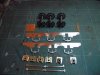
As mentioned before the frame plates were shortened and the etched axle box springs removed to allow LG white metal ones to be fitted. These will be fixed to the frames by means of 12ba bolts and as such the frames were marked and drilled for these and the castings cleaned up. The leading and centre horn blocks are meteor models and the rear are col Dowling's insulated ones, to allow split axle current collection as previously mentioned. Because of this the pre etched holes for plunger pick ups were not needed and filled with brass bar. Frame spacers were cut from material supplied by the S7 Stores and finally the coupling rods were made up. These are the usual laminations and do look quite hefty, which is what I was after. The only addition here was the oil pot top where the coupling rods meet in the centre, this for some reason was not etched in the kit but it's a few moments to add so no worries there. It just needs a cork now. The coupling rods have been drilled to allow the slater's crank pin bearings to fit with them and I will have a go with the crank pin nuts the S7 stores supply this time and see how they go. Any way onto the pictures, here's what I'm looking for with the coupling rods etc;


And here's the bits all laid out ready to put together

Crap photo's I know, I need a larger lamp for my bench! The frames tacked together with the spacers

I know they look flimsy here and they are really but the cylinder block front and rear, motion plate and rear frame stretcher (which will probably secure the gear box) will stiffen things up nicely. Talking of gear boxes, any idea's Steph? Horn blocks fitted and wheels in

No tight spots and hopefully you get the idea with the crank pins how they will look. And I couldn't resist just a quick pose of the body on. Latest work on the body is the lamp irons fitted front and rear and the cab roof rolled and laminated together. All is still loose but now the frames are together I can fit the boiler and smoke box which will allow me to sort out the position of the cylinder block etc

She looks daft without guard irons steps and all the below footplate detail, but I'll soon sort that,
ATB Mick
As mentioned before the frame plates were shortened and the etched axle box springs removed to allow LG white metal ones to be fitted. These will be fixed to the frames by means of 12ba bolts and as such the frames were marked and drilled for these and the castings cleaned up. The leading and centre horn blocks are meteor models and the rear are col Dowling's insulated ones, to allow split axle current collection as previously mentioned. Because of this the pre etched holes for plunger pick ups were not needed and filled with brass bar. Frame spacers were cut from material supplied by the S7 Stores and finally the coupling rods were made up. These are the usual laminations and do look quite hefty, which is what I was after. The only addition here was the oil pot top where the coupling rods meet in the centre, this for some reason was not etched in the kit but it's a few moments to add so no worries there. It just needs a cork now. The coupling rods have been drilled to allow the slater's crank pin bearings to fit with them and I will have a go with the crank pin nuts the S7 stores supply this time and see how they go. Any way onto the pictures, here's what I'm looking for with the coupling rods etc;
And here's the bits all laid out ready to put together
Crap photo's I know, I need a larger lamp for my bench! The frames tacked together with the spacers
I know they look flimsy here and they are really but the cylinder block front and rear, motion plate and rear frame stretcher (which will probably secure the gear box) will stiffen things up nicely. Talking of gear boxes, any idea's Steph? Horn blocks fitted and wheels in
No tight spots and hopefully you get the idea with the crank pins how they will look. And I couldn't resist just a quick pose of the body on. Latest work on the body is the lamp irons fitted front and rear and the cab roof rolled and laminated together. All is still loose but now the frames are together I can fit the boiler and smoke box which will allow me to sort out the position of the cylinder block etc
She looks daft without guard irons steps and all the below footplate detail, but I'll soon sort that,
ATB Mick
Attachments
micknich2003
Western Thunderer
Mick, it's looking good.
7mmMick
Western Thunderer
Can I ask whose hornblocks/bearings are in use, why only the rearmost set are insulated and why the screws aren't in place for the centre ones, once fitted?
This answer has a strong Yorkshire theme and centres really around me being tight/economical. I have a stock of meteor models horn guides and blocks, which are the all brass ones here and not wishing to waste them I used those for the centre and front axles. Plus these can be seen between the frames when looking from above and because they have an element of detail I wanted to use those. The rear ones are milled brass guides, supplied by Col Dowling ( Eastsidepilot of this parish ) that utilise the Slater's insulated horn blocks. So the pick up works by collecting from the front and centre and travelling to the coupling rod and then onto the rear driver's which are shorted through to collect current from the rear axle only. No complications then with the crank ( or soon to be ) centre axle etc. I used this method on my J73 and it worked really well, so i'm trying it again here. The screws are not in place for no real reason really, the centre horn guides are 2mm higher than the front and rear so the centre axle is afforded upward travel as well as down, which I have found is essential,
ATB Mick
7mmMick
Western Thunderer
Another little update from tonights work. I talked yesterday about fitting the splashers etc and tonight I got round to doing so. First job was to fit a JB tube plate, which isn't quite right, but close enough and offers the appearance i'm after. I hasten to add that's nowt to do with JB, it's just this one is designed for a larger loco and I've fudged it a little However if you get a magnifiying glass and count the tubes there are a few too many )")

Once this was fitted I secured the boiler to the smoke box, fitted the splashers, which have a lovely riveted etch around the bottom which looks spot on I think. Then I went on to fit the dome, safety valve bonnet and whistle. It took a fair while with the wet and dry to improve the fit of these and the dome isn't as nice as i'd like but I started to loose the profile because i'd removed too much material. So the fit now is a trade off really. Oh and I straightened up the sandbox lid as it was skew if One good thing about these photos is that they show up and glaring errors

I have stalled a bit now as I am out of stock of 1mm angle and need some to fit around the boiler at the cab end to act as a means of securing it on a temporary basis and allow the boiler to be removable for painting,
ATB Mick
However if you get a magnifiying glass and count the tubes there are a few too many Once this was fitted I secured the boiler to the smoke box, fitted the splashers, which have a lovely riveted etch around the bottom which looks spot on I think. Then I went on to fit the dome, safety valve bonnet and whistle. It took a fair while with the wet and dry to improve the fit of these and the dome isn't as nice as i'd like but I started to loose the profile because i'd removed too much material. So the fit now is a trade off really. Oh and I straightened up the sandbox lid as it was skew if
One good thing about these photos is that they show up and glaring errorsI have stalled a bit now as I am out of stock of 1mm angle and need some to fit around the boiler at the cab end to act as a means of securing it on a temporary basis and allow the boiler to be removable for painting,
ATB Mick
Last edited:

adrian
Flying Squad
That is coming along a treat, some nice touches and very clean work. The lamp irons look very good castings are they Laurie Griffin ones?
Have I understood correctly, are you intending the angle to be curved around the boiler? To be honest I'd be wary of doing this with angle, due to it's inherent structural design angle is never very happy being curved and I've often found it's often more trouble than it's worth as it distorts too much. I usually would cut a curved strip for the cab and separate strip around the boiler, unless you have a cunning plan.I have stalled a bit now as I am out of stock of 1mm angle and need some to fit around the boiler at the cab end to act as a means of securing it on a temporary basis and allow the boiler to be removable for painting,