JimG
Western Thunderer
This all started as a completely different project. I started developing an etched kit for a 16T mineral wagon body kit for the S Scale Society using official drawings which AndyB got for me. But that came to a halt when the cost of new photo tools became a bit high.
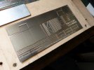
I was trying to reproduce the 1/4" thickness of the prototype's steel sheet which meant a lot of half etching of 8 thou nickel silver sheet and it became very finnicky to build and I was envisaging the "Who the hell designed this" comments.
I had a bit of a conscience about not proceeding with this etch. The SSMRS did have a white metal kit for a 16T body but no proper underframe to go with it, most people using an LMS 16' 6"/9' WB etch which was sort of close. So I thought that we should have a proper underframe for the body kit and I commissioned Justin Newitt (Rumney Models) to produce one - which he did and a nice job too. Then we ran out of body kits and I had no luck in getting any more produced. So the body etch development was started to give an alternative which would use Justin's underframe and hopefully reward him with further sales.
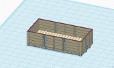
So my broken hip and Covid experience intervened and then I started thinking about maybe doing a 3D print of the body and I started doodling in Fusion 360 and produced a first attempt which actually printed fairly well but needed a bit of work. Then the printer broke down and I spent a few months trying to repair it - the fault was in the LCD screen which had become obsolete and it took time to find a replacement which needed a lot of upgrading of the electronics - all of which didn't work!! So I had to bite the bullet and get a new printer. I then opened up Fusion 360 to start work on the print again. This was around the time that AutoDesk was limiting the free version and for some reason I lost my drawing file in the small hassle when adjusting to the restrictions. So I went right off Fusion 360 and started to use Solid Edge Community Edition and had to start at square one with the drawing - and also learn a completely new CAD package.
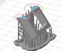
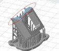
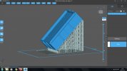
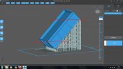
I was aiming to print the wagon oriented at around 40 degrees with the end door at the top so that the majority of of the overhangs and protrusions would not require supporting. I started off with an 0.6mm side thickness and left the floor out since I wanted to experiment wiht a metal floor to increase the weight of the body. But I ran into problems with peculiar ridging on the sides and tried adding a temporary floor to get rid of the ridging, as well as increasing the thickness of the sides.
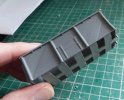
The faults are obvious here, going from lower left to upper right on the sides. (The other lines crossing them were caused by dirt on the LCD.) So after umpteen attempts with various types of false floors and varying thicknesses of the sides I gave up on the 40 degree orentation and started printing with the body sitting flat on the build plate. That got rid of the ridging on the sides, but the supporting of all the protrusions and overhands became necessary. So there were another lot of attempts until i started getting success.
I now support the wagon as follows :-
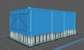
The body is supported on medium weight supports sitting 6mm off the plate.
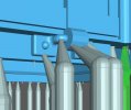
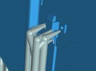
The details on the side doors are added using light supports with the finest ends which will work with the resin.
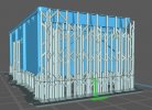
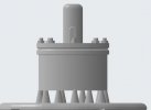
All the protrusions on the end doors use light supports.
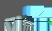
The top angle and corner brackets are supported all round the body.
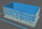
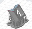
And the final result is this - quite a forest of supports.
I have also experimented with increasing the pitch between supports to cut the number down, and I might try going wider pitch than this.
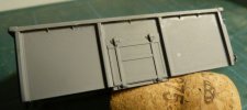
The end results I've eventually got are
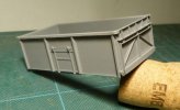
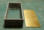
And the body with the brass floor - cut on my CNC machine with the floor plating engraved.
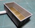
I'm pleasantly surprised that there is pretty well no bowing of the sides. The weight of the body and floor is 44 grams, so the complete wagon could be around 60 grams or more.
The final thickness of the sides is 1.2mm tapering to 0.6mm at the top - you can just see the ridge lines on the inner sides. The brass floor is 1.6mm thick. So floor and sides are well over scale thickness but all the extra is on the inside and hardly shows.
Apologies for the poor paint job. I gave it a quick scoosh of Halford's grey primer to make it photograph better and the weather outside wasn't great and the can got a bit close. I also slightly messed up the top girder over the end door when cleaning off the supports. Must do better next time.
This is a quick lash-up to take to the SSMRS AGM in a week's time to get feedback. I've got one of Justin's underframes to build to go under the body as well.
I've been talking about this to Richard (Dikitriki) for what seems to be months now and keep promising to put a picture up on WT to show progress. Well here it is.
Jim.
PS


I was trying to reproduce the 1/4" thickness of the prototype's steel sheet which meant a lot of half etching of 8 thou nickel silver sheet and it became very finnicky to build and I was envisaging the "Who the hell designed this" comments.

I had a bit of a conscience about not proceeding with this etch. The SSMRS did have a white metal kit for a 16T body but no proper underframe to go with it, most people using an LMS 16' 6"/9' WB etch which was sort of close. So I thought that we should have a proper underframe for the body kit and I commissioned Justin Newitt (Rumney Models) to produce one - which he did and a nice job too. Then we ran out of body kits and I had no luck in getting any more produced. So the body etch development was started to give an alternative which would use Justin's underframe and hopefully reward him with further sales.
So my broken hip and Covid experience intervened and then I started thinking about maybe doing a 3D print of the body and I started doodling in Fusion 360 and produced a first attempt which actually printed fairly well but needed a bit of work. Then the printer broke down and I spent a few months trying to repair it - the fault was in the LCD screen which had become obsolete and it took time to find a replacement which needed a lot of upgrading of the electronics - all of which didn't work!! So I had to bite the bullet and get a new printer.
 I then opened up Fusion 360 to start work on the print again. This was around the time that AutoDesk was limiting the free version and for some reason I lost my drawing file in the small hassle when adjusting to the restrictions. So I went right off Fusion 360 and started to use Solid Edge Community Edition and had to start at square one with the drawing - and also learn a completely new CAD package.
I was aiming to print the wagon oriented at around 40 degrees with the end door at the top so that the majority of of the overhangs and protrusions would not require supporting. I started off with an 0.6mm side thickness and left the floor out since I wanted to experiment wiht a metal floor to increase the weight of the body. But I ran into problems with peculiar ridging on the sides and tried adding a temporary floor to get rid of the ridging, as well as increasing the thickness of the sides.

The faults are obvious here, going from lower left to upper right on the sides. (The other lines crossing them were caused by dirt on the LCD.) So after umpteen attempts with various types of false floors and varying thicknesses of the sides I gave up on the 40 degree orentation and started printing with the body sitting flat on the build plate. That got rid of the ridging on the sides, but the supporting of all the protrusions and overhands became necessary. So there were another lot of attempts until i started getting success.
I now support the wagon as follows :-

The body is supported on medium weight supports sitting 6mm off the plate.


The details on the side doors are added using light supports with the finest ends which will work with the resin.

All the protrusions on the end doors use light supports.

The top angle and corner brackets are supported all round the body.

And the final result is this - quite a forest of supports.

I have also experimented with increasing the pitch between supports to cut the number down, and I might try going wider pitch than this.

The end results I've eventually got are


And the body with the brass floor - cut on my CNC machine with the floor plating engraved.


I'm pleasantly surprised that there is pretty well no bowing of the sides. The weight of the body and floor is 44 grams, so the complete wagon could be around 60 grams or more.
The final thickness of the sides is 1.2mm tapering to 0.6mm at the top - you can just see the ridge lines on the inner sides. The brass floor is 1.6mm thick. So floor and sides are well over scale thickness but all the extra is on the inside and hardly shows.
Apologies for the poor paint job. I gave it a quick scoosh of Halford's grey primer to make it photograph better and the weather outside wasn't great and the can got a bit close.
 I also slightly messed up the top girder over the end door when cleaning off the supports. Must do better next time.
This is a quick lash-up to take to the SSMRS AGM in a week's time to get feedback. I've got one of Justin's underframes to build to go under the body as well.
I've been talking about this to Richard (Dikitriki) for what seems to be months now and keep promising to put a picture up on WT to show progress. Well here it is.

Jim.
PS


Last edited:


