oldravendale
Western Thunderer
I've been building occasional semaphore signals off and on for club over the last two or three years. Now we have most of the single signal posts and brackets in place we need some significant gantries. I didn't volunteer, as I thought such construction would be beyond me, but initially having been asked to create a single but long and complicated gantry over the semi-sceneicked (is that a word) fiddle yard this morphed in to two gantries dealing individually with traffic in each direction - still a significant task but easier to get my head around and being in the fiddle yard an opportunity to develop techniques before moving on to the properly scenic areas and engine shed. Although we have the electronic repeaters on the control panels we want to have a visual confirmation of the route set.
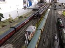
I then pondered for a month, looking through my signalling books from time to time and talking to Dikitriki about the gantry on Heyside which remains an inspiration but will go on one side for the moment - the principle may well be used for the second gantry. Right now this is taking precedence over a certain rebuilt Royal Scot which remains languishing in the workshop, any progress on that being delayed by building works, which blocked the workshop with furniture and tat for the last year or so. Fortunately that's now completed and much of the tat has gone on to ebay. Additionally there is a certain photographic collection which absorbs significant amounts of time.
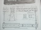
However, during research I came across a footbridge with signals attached. I can't remember precisely where - the location will have to wait until I get out to the workshop which will await the end of the current monsoon. The fiddle yard includes a loco and carriage servicing facility but currently with no access. (Actually access could be made from the station ramp so I've chosen to ignore that). I remember with fondness the footbridge over the GWR line at Southall - the Bridge of Doom - which provided access to the shed as well as a pedestrian route across the railway. Some of the photos at Southall in the Tim Mills' collection show sections of this. Whilst the fiddle yard does not allow a prototypical reproduction it has many of the features which could make it work - and the required signalling could be attached so the next question was how to achieve this. (That signal box doesn't actually live on the turntable. Significant trackwork modifications were in hand at the time of the photos and some buildings had been moved... ).
).
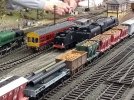
We already had a station footbridge from the York Modelmaking kit, not built by me.
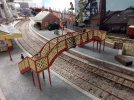
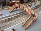
Hooray! There were some bits left over which were handed to me "just on the off chance they may give you an idea or two". So this is the section which has to be bridged, with a pedestrian route across the whole set up and a secondary route to the loco servicing facility. It will allow for considerable invention, possibly with access on the skew, straightening up somewhere about half way across.
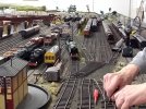
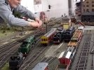
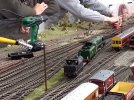
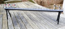
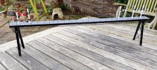
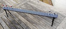
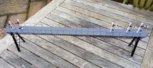
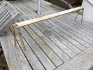
I've now created a first "proof of concept" using the scrap components. The void under the footway is to accommodate servos and electrical services.
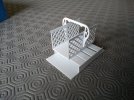
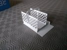
The rather cumbersome outriggers will be replaced with boarding, posts and rod rails and the verticals of the box with metal section - possibly I section - as this will need considerable strength over any unsupported length. This will allow removal of the present base which will give access for the installation and maintenance of the servos and mounting points for the signal posts from underneath.
Progress will be slow and intermittent. When and if there is a "proof of concept Mk II" it'll be on here but my immediate task is to measure the basic dimensions and get the crayons out (they don't allow anything sharp in here) to produce some sort of drawing of the components required. I'll visit the York Show this Easter - very conveniently my cousin lives in York so that solves the accommodation issues. York Modelmaking are an attendee so I'll have the opportunity to discuss the potential requirements with them. (Jolly nice people they are judging by my previous conversations with them).
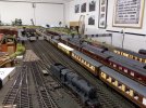
Looking way in to the future there will need to be a second gantry, probably replacing the line identifiers as seen below. We'll still need to identify each track but I'll try to incorporate that in to the design when I get to it. I'm thinking of some sort of regular lattice construction but that may well change.
Brian

I then pondered for a month, looking through my signalling books from time to time and talking to Dikitriki about the gantry on Heyside which remains an inspiration but will go on one side for the moment - the principle may well be used for the second gantry. Right now this is taking precedence over a certain rebuilt Royal Scot which remains languishing in the workshop, any progress on that being delayed by building works, which blocked the workshop with furniture and tat for the last year or so. Fortunately that's now completed and much of the tat has gone on to ebay. Additionally there is a certain photographic collection which absorbs significant amounts of time.
However, during research I came across a footbridge with signals attached. I can't remember precisely where - the location will have to wait until I get out to the workshop which will await the end of the current monsoon. The fiddle yard includes a loco and carriage servicing facility but currently with no access. (Actually access could be made from the station ramp so I've chosen to ignore that). I remember with fondness the footbridge over the GWR line at Southall - the Bridge of Doom - which provided access to the shed as well as a pedestrian route across the railway. Some of the photos at Southall in the Tim Mills' collection show sections of this. Whilst the fiddle yard does not allow a prototypical reproduction it has many of the features which could make it work - and the required signalling could be attached so the next question was how to achieve this. (That signal box doesn't actually live on the turntable. Significant trackwork modifications were in hand at the time of the photos and some buildings had been moved...
 ).
).
We already had a station footbridge from the York Modelmaking kit, not built by me.


Hooray! There were some bits left over which were handed to me "just on the off chance they may give you an idea or two". So this is the section which has to be bridged, with a pedestrian route across the whole set up and a secondary route to the loco servicing facility. It will allow for considerable invention, possibly with access on the skew, straightening up somewhere about half way across.


I've now created a first "proof of concept" using the scrap components. The void under the footway is to accommodate servos and electrical services.


The rather cumbersome outriggers will be replaced with boarding, posts and rod rails and the verticals of the box with metal section - possibly I section - as this will need considerable strength over any unsupported length. This will allow removal of the present base which will give access for the installation and maintenance of the servos and mounting points for the signal posts from underneath.
Progress will be slow and intermittent. When and if there is a "proof of concept Mk II" it'll be on here but my immediate task is to measure the basic dimensions and get the crayons out (they don't allow anything sharp in here) to produce some sort of drawing of the components required. I'll visit the York Show this Easter - very conveniently my cousin lives in York so that solves the accommodation issues. York Modelmaking are an attendee so I'll have the opportunity to discuss the potential requirements with them. (Jolly nice people they are judging by my previous conversations with them).
Looking way in to the future there will need to be a second gantry, probably replacing the line identifiers as seen below. We'll still need to identify each track but I'll try to incorporate that in to the design when I get to it. I'm thinking of some sort of regular lattice construction but that may well change.

Brian
Last edited:


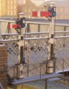
 I'd truly not recognised the origin of the species. I must have picked it up by osmosis or something. However your construction is actually very helpful. Just one question - how does the lamp lighter get to the lamps? I guess he just leans over the footbridge balustrade or maybe stands on it to reach them
 . Mine will have his own walkway - so there! He'll be much safer.

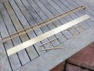
 so out came the gas axe. Fortunately I was able to use all the parts by shortening them and cleaning up.