You are using an out of date browser. It may not display this or other websites correctly.
You should upgrade or use an alternative browser.
You should upgrade or use an alternative browser.
A newby's attempt at building a Micromodels Card kit.
- Thread starter Mike Trice
- Start date
Mike Trice
Western Thunderer
That looks pretty good. Bear in mind I already have LS1 in my collection, it is just LSII I missing (and the track).
Thanks for going to the effort to upload these.
Thanks for going to the effort to upload these.
daifly
Western Thunderer
I suggested creating a .pdf from the original scan. If you’ve already got a rubbish .jpg then turning it into a .pdf won’t improve it!If you created the pdf by downloading the Western Thunder image, changing resolution than converting to pdf as suggested previously the quality of the image has definately been downgraded.
Dave
Think i`ve posted most of them in pdf,got a bit confusing with the different formats.That looks pretty good. Bear in mind I already have LS1 in my collection, it is just LSII I missing (and the track).
Thanks for going to the effort to upload these.
Attachments
Last edited:
Mike Trice
Western Thunderer
@sagaguy it worries me that you have pdf's with 96dpi in the name.
The dpi figure says how many dots per inch are in the image. The higher the dpi the better quality the image however just chaging the dpi in a graphics editor may not achieve what you hope.
Have a look at the following image trying to compare various images.
The image on the left has been scanned at 300 dpi (I often scan higher than that, up to 1200dpi).
The image in the middle had been reduced to 96 dpi but shown at the same enlargement. As the image can hold less information the quality is much poorer.
The image on the right has been adjusted from 96dpi back to 300 dpi. Note that increasing the dpi from the inferior 96dpi image does not improve the quality in the final image as it is based on an already reduced quality starting point.
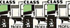
To get reasonable quality you need to keep to 300dpi. When saving something as a pdf the software often defaults to 96dpi but this can usually be overridden.
The dpi figure says how many dots per inch are in the image. The higher the dpi the better quality the image however just chaging the dpi in a graphics editor may not achieve what you hope.
Have a look at the following image trying to compare various images.
The image on the left has been scanned at 300 dpi (I often scan higher than that, up to 1200dpi).
The image in the middle had been reduced to 96 dpi but shown at the same enlargement. As the image can hold less information the quality is much poorer.
The image on the right has been adjusted from 96dpi back to 300 dpi. Note that increasing the dpi from the inferior 96dpi image does not improve the quality in the final image as it is based on an already reduced quality starting point.

To get reasonable quality you need to keep to 300dpi. When saving something as a pdf the software often defaults to 96dpi but this can usually be overridden.
Mike Trice
Western Thunderer
There is a high likelihood I would never get around to using them so as I already have LS1, you can probably save yourself some work and not worry. But thanks for the offer anyway.
Mike Trice
Western Thunderer
Mike Trice
Western Thunderer
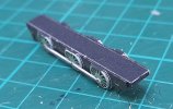
The proof of the pudding so to speak. Original sideframes and new coupling rod prints laminated to double thickness and the orighinal coupling rods painted out:
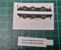
With the new wheels and coupling rods assembled on the sideframe:
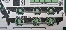
The chassis (hopefully) is closer to scale at the models 1/186 sizing:
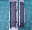
Comparing the overwide width of the original chassis on the left with the new scale version on the right.

With the new wheels and coupling rods assembled on the sideframe:

The chassis (hopefully) is closer to scale at the models 1/186 sizing:

Comparing the overwide width of the original chassis on the left with the new scale version on the right.

adrian
Flying Squad
Thanks for that - as mentioned before the pdf has to start with the high resolution image (it can't improve the image quality) but then any pdf creation software will have settings to adjust the image quality. As the extension says it's a Portable Document Format - it was designed to create documents to transfer so it will usually try to reduce the image quality where possible to reduce the size and increase portability. So usually you do have to go in and fiddle with the settings to stop it down scaling the image quality.Note the "Adobe PDF Preset" has been set to "[High Quality Print]". Select the "Compression" tab then change "Options" to "Do Not Downsample"
Mike Trice
Western Thunderer
Time for an update.
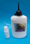
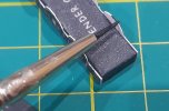
I had previously asked @Terry what glue he used. The answer was Cosmic Shimmer Specialist Acrylic Glue so I ordered a bottle online. It has proved a very nice glue to use with quite a quick grab time. At the same time I also ordered some precision tip applicators which work extremely well with the Cosmic glue and I have managed to abandon using a cocktail stick to apply it. The wire "pricker" was made so I could unblock the applicators nozzle which I have needed to do about once a week:
I hit a bit of a dilema relating to how to physically join corners on these models. A butt joint was the most obvious but would result in either the item being too wide (if the sides overlap the ends) or too long (if the ends overlap the sides). I could find no reference in the supplied Micromodels kit instructions nor anything online.
Eventually I discovered the following extract from the "Making Models in Card" booklet:
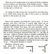
It appears I have been making these kits all wrong, from cutting to joining.
For scoring I have used the back of the scalpel blade which if too heavy handed can result in a weak joint. It also tends to damage the printed surface somewhat. I decided to try using an engineer's scriber held at a low angle and the results have been much better as the following exercise will hopefully illustrate.
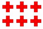
So how to form 45 degree bevelled edges to the card parts? The booklet mentions sanding the parts once cut, which I admit I have not tried, though I have on occasion resorted to filing/sanding to true parts up. It seemed to me that it should be possible to cut the parts out by holding the scalpel at a 45 degree (ish) angle against a straight edge. Clearly some experimentation was called for. So I put together some basic artwork in Inkscape using 10mm squares. The outline was 0.2mm with the actual 10mm measurement to the centre of the line, if that makes sense:
The first "cube" was made up by cutting the shape along the outside of the external edges, the scoring done with the reversed scalpel blade and the corner joint butted:
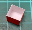
When viewed from the side it is obvious that the cube will be 10.6mm wide (2 * side thickness + 2 * half line thickness) rather than the intended 10mm. Note also how the side deforms as the folding process results in an overwide top.
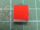
The damage by scoring with the scalpel blade is also very evident as the card actually opens up at the fold resulting in visible white card:
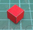
Next I changed my approach. I cut the external joint faces at approx 45 degree trying to use the centre of the printed line:
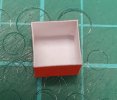
Scoring was done using the engineer's scriber and has resulted in a much neater finish with less damage and a stronger fold line. I also scribed slightly inboard of the top lines:
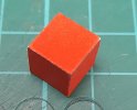
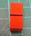
The result is far neater and I could probably get away with minimum touching in to hide the while card. The interesting thing is to compare the two cubes side by side, one is visibly bigger than the other. Does this matter? It can as I recently discovered with a model where the firebox would not fit between the sidetanks using my original method, but fitted comfortably using the bevelling method:
So I need to put this to the test on a real model, but which one. I thought I would have another go at the GNR Atlantic featured at the start of this topic however as I discovered the Micromodel kits have overscale track gauge. So should I correct this as part of my build?
Short term I have decided to give a Modelcraft Micromodel as go as they use a narrower inner chassis. That might help me decide whether to adapt the GNR Atlantic. Strangely it also looks as if it might be easier to put together and is pretty close to my preferred scale of 1/200:
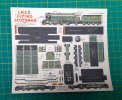
So I took an original Modelcraft card and scanned it. I turned off any attempt by the scanner to colour correct the scan and tried to get the scan as close to the original as possible. On previous models I have been using some generic 160gsm card stock off the internet and it is OK but not brilliant, so this time I have printed the model on some Bristol paper (which also claims to be 160gsm) to see how it compares. Once printed the sheet is sprayed with varnish to help seal the inks and provide a degree of UV protection. I will report how I get on.
I had previously asked @Terry what glue he used. The answer was Cosmic Shimmer Specialist Acrylic Glue so I ordered a bottle online. It has proved a very nice glue to use with quite a quick grab time. At the same time I also ordered some precision tip applicators which work extremely well with the Cosmic glue and I have managed to abandon using a cocktail stick to apply it. The wire "pricker" was made so I could unblock the applicators nozzle which I have needed to do about once a week:

I hit a bit of a dilema relating to how to physically join corners on these models. A butt joint was the most obvious but would result in either the item being too wide (if the sides overlap the ends) or too long (if the ends overlap the sides). I could find no reference in the supplied Micromodels kit instructions nor anything online.
Eventually I discovered the following extract from the "Making Models in Card" booklet:

It appears I have been making these kits all wrong, from cutting to joining.
For scoring I have used the back of the scalpel blade which if too heavy handed can result in a weak joint. It also tends to damage the printed surface somewhat. I decided to try using an engineer's scriber held at a low angle and the results have been much better as the following exercise will hopefully illustrate.
So how to form 45 degree bevelled edges to the card parts? The booklet mentions sanding the parts once cut, which I admit I have not tried, though I have on occasion resorted to filing/sanding to true parts up. It seemed to me that it should be possible to cut the parts out by holding the scalpel at a 45 degree (ish) angle against a straight edge. Clearly some experimentation was called for. So I put together some basic artwork in Inkscape using 10mm squares. The outline was 0.2mm with the actual 10mm measurement to the centre of the line, if that makes sense:

The first "cube" was made up by cutting the shape along the outside of the external edges, the scoring done with the reversed scalpel blade and the corner joint butted:

When viewed from the side it is obvious that the cube will be 10.6mm wide (2 * side thickness + 2 * half line thickness) rather than the intended 10mm. Note also how the side deforms as the folding process results in an overwide top.

The damage by scoring with the scalpel blade is also very evident as the card actually opens up at the fold resulting in visible white card:

Next I changed my approach. I cut the external joint faces at approx 45 degree trying to use the centre of the printed line:

Scoring was done using the engineer's scriber and has resulted in a much neater finish with less damage and a stronger fold line. I also scribed slightly inboard of the top lines:

The result is far neater and I could probably get away with minimum touching in to hide the while card. The interesting thing is to compare the two cubes side by side, one is visibly bigger than the other. Does this matter? It can as I recently discovered with a model where the firebox would not fit between the sidetanks using my original method, but fitted comfortably using the bevelling method:

So I need to put this to the test on a real model, but which one. I thought I would have another go at the GNR Atlantic featured at the start of this topic however as I discovered the Micromodel kits have overscale track gauge. So should I correct this as part of my build?
Short term I have decided to give a Modelcraft Micromodel as go as they use a narrower inner chassis. That might help me decide whether to adapt the GNR Atlantic. Strangely it also looks as if it might be easier to put together and is pretty close to my preferred scale of 1/200:

So I took an original Modelcraft card and scanned it. I turned off any attempt by the scanner to colour correct the scan and tried to get the scan as close to the original as possible. On previous models I have been using some generic 160gsm card stock off the internet and it is OK but not brilliant, so this time I have printed the model on some Bristol paper (which also claims to be 160gsm) to see how it compares. Once printed the sheet is sprayed with varnish to help seal the inks and provide a degree of UV protection. I will report how I get on.
Last edited:
Mike Trice
Western Thunderer
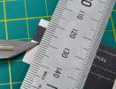
Contrived photo to show the knife blade being held at an angle to the card during cutting:
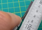
Likewise the shallow angle of the scriber. Bristol paper seems to need more pressure when scoring:
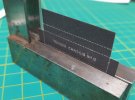
A pair of Engineer's Squares can be used as impromptu bending bars (which in my case would be a lot easier if they were a matching pair):
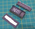
So far so good. Strangely the kit does not supply the tender footplate but it is easily cut from spare card:
When colouring in the edges I hold a spotting brush low from behind the visible surface effectively just using the side of the brush. I also don't use black paint but rather Vallejo Black Grey which tones in with the printed black areas better:
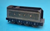
All the main parts together:
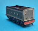
From certain angles it is evident that the wheels and sideframes are inset a lot. The wheels are where they should be which will suit scale (ish) track but to improve the look I will have to add sideframe overlays to improve the look. I will also add card punchings to give the wheels some profile.
Where a single layer is used the represent outside frames and the wheels the kit designers have to decide whether to set the wheels in the correct location or the sideframes. This kit has gone for the wheels being correct (which I prefer) whereas Micromodels set them at the outer dimension resulting in too wide a track gauge:
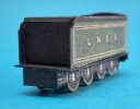
Let's see how the loco turns out.
P.S. Annoyingly the two sets of wheels/sideframes provided don't match exactly. Producing these digitally would be a doddle, draw one and mirror it. Unfortunately these predate this capability so it is down to the skill/attention of the draftsperson.

Likewise the shallow angle of the scriber. Bristol paper seems to need more pressure when scoring:

A pair of Engineer's Squares can be used as impromptu bending bars (which in my case would be a lot easier if they were a matching pair):

So far so good. Strangely the kit does not supply the tender footplate but it is easily cut from spare card:

When colouring in the edges I hold a spotting brush low from behind the visible surface effectively just using the side of the brush. I also don't use black paint but rather Vallejo Black Grey which tones in with the printed black areas better:

All the main parts together:


From certain angles it is evident that the wheels and sideframes are inset a lot. The wheels are where they should be which will suit scale (ish) track but to improve the look I will have to add sideframe overlays to improve the look. I will also add card punchings to give the wheels some profile.
Where a single layer is used the represent outside frames and the wheels the kit designers have to decide whether to set the wheels in the correct location or the sideframes. This kit has gone for the wheels being correct (which I prefer) whereas Micromodels set them at the outer dimension resulting in too wide a track gauge:

Let's see how the loco turns out.
P.S. Annoyingly the two sets of wheels/sideframes provided don't match exactly. Producing these digitally would be a doddle, draw one and mirror it. Unfortunately these predate this capability so it is down to the skill/attention of the draftsperson.
Mike Trice
Western Thunderer
Sometimes less is more!
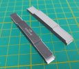
The original chassis design is a complex fold up affair which requires the top surface to be shaped to suit the profile. This is very fiddly to do and resulted in a chassis block that was skewed along its length. To get around this I created an alternative block that folded up into a simple "U" shape and laminated up strips of mount board to give it strength:
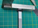
Unlike the original chassis design I dispensed with the top layer and decided to fix the footplate to the chassis block directly. Doubting my abilities to get the profile good I decided to split the footplate into 3 sections. The first section was the buffer beam and first curve:
With the buffer beam stuck the curved section was pried up and glue applied then pushed down onto the chassis:
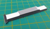
Next I split the remaining footplate in the middle so I could tackle just the front curve. This went without incident and was glued in place:
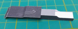
Finally the rear section was dealt with, again without incident:
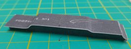
With all the visible edges touched in the wheels were added forming the basic unit:

The original chassis design is a complex fold up affair which requires the top surface to be shaped to suit the profile. This is very fiddly to do and resulted in a chassis block that was skewed along its length. To get around this I created an alternative block that folded up into a simple "U" shape and laminated up strips of mount board to give it strength:

Unlike the original chassis design I dispensed with the top layer and decided to fix the footplate to the chassis block directly. Doubting my abilities to get the profile good I decided to split the footplate into 3 sections. The first section was the buffer beam and first curve:

With the buffer beam stuck the curved section was pried up and glue applied then pushed down onto the chassis:

Next I split the remaining footplate in the middle so I could tackle just the front curve. This went without incident and was glued in place:

Finally the rear section was dealt with, again without incident:

With all the visible edges touched in the wheels were added forming the basic unit:

michael mott
Western Thunderer
Mike it looks like your patience and experiments are paying dividends. The tests with the cube was a brilliant idea. The current chassis looks great!
Michael
Michael
Mike Trice
Western Thunderer
On to the boiler. The boilers of A1/A3s has a distinctive shape being parallel from the smokebox, then tapering upwards towards the firebox then tapering back to the cab. The weight diagram shows this:

The supplied boiler looks like this. It looks as if some attempt has been made to introduce these tapers, albeit from the wrong position, but I really could not see how it would produce the required shape:
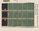
Ans so it turned out in reality. My next attempt was to modify the design of the boiler thus:
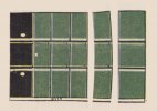
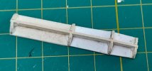
The individual parts were rolled and joining strips added:
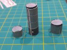
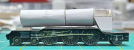
After joining them together I got:
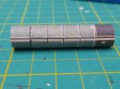
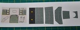
Ok, the shape could be better. The firebox has an overlay to give the distinctive shape at the rear end. This was formed using a mounting board back former to match the cab:
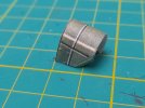
The overlay is then supposed to overlay the boiler. The instructions are very vague in this area. The result is appalling and clearly does not match the footplate. I subsequently found the boiler is 2mm too large a diameter which does not help it sit down enough. The overlay does not carry through the handrail either:
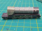
I suspect this might take some time to resolve, assuming I can be bothered.

The supplied boiler looks like this. It looks as if some attempt has been made to introduce these tapers, albeit from the wrong position, but I really could not see how it would produce the required shape:

Ans so it turned out in reality. My next attempt was to modify the design of the boiler thus:

The individual parts were rolled and joining strips added:

After joining them together I got:

Ok, the shape could be better. The firebox has an overlay to give the distinctive shape at the rear end. This was formed using a mounting board back former to match the cab:

The overlay is then supposed to overlay the boiler. The instructions are very vague in this area. The result is appalling and clearly does not match the footplate. I subsequently found the boiler is 2mm too large a diameter which does not help it sit down enough. The overlay does not carry through the handrail either:

I suspect this might take some time to resolve, assuming I can be bothered.
Mike Trice
Western Thunderer
Mike Trice
Western Thunderer
Brian McKenzie
Western Thunderer
The crosshead will smash into the front mounting of the slidebars - before the wheels can rotate fully. 


Mike Trice
Western Thunderer
True.
Second prototype has a different approach. I produced paper core by winding and gluing around a round pencil:
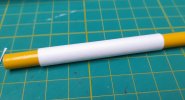
The core was treated with French Polish (Shellac) to harden it a bit, then a thin strip wound around the widest part to act as a former.
Various overlays later:
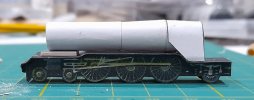
Rear firebox could be glued more accurately. I am also finding it difficult to curve the card without getting wrinkles. Next build will feature a wooden dowel core.
Next step is to combine the new panels with the original card model. I might just tweak the valve gear at the same time ;-)
Second prototype has a different approach. I produced paper core by winding and gluing around a round pencil:

The core was treated with French Polish (Shellac) to harden it a bit, then a thin strip wound around the widest part to act as a former.
Various overlays later:

Rear firebox could be glued more accurately. I am also finding it difficult to curve the card without getting wrinkles. Next build will feature a wooden dowel core.
Next step is to combine the new panels with the original card model. I might just tweak the valve gear at the same time ;-)

