So - what's happened since I last posted about the build process itself?
The vee-hanger, cross shaft and tumbler assembly has been made up and soldered in place. The vee hanger is the kit's, the cross shaft is a couple of pieces of tube with 0.9mm wire through, and the tumbler is an Ambis part:

The inner end of the wire represents the single vertical support of the prototype.
Next, the brake lever guard - this is from the kit:


It fits nicely into the slots etched into the solebar, and makes up to a nice solid part. The ratchet isn't correct, as it should a flat section, not a T, but making these as per the prototype is rather tricky, as the metalwork has to have two 90-degree twists in it, above and below the ratchet. Anyway, this is all good, right?
Well, no. The Curse of the Serpent struck again - turns out, the lever guard is in the wrong place, and would foul with the bearing spring shoe. Of course, I realised this after I had done it and was doing a quick check of how the springs fit with the axle guard units. So, the old guard had to be removed, the holes filled, new slots drilled and hacked out with the end of a sharp needle file, and a new guard made up and fitted, a few mm closer to the centre of the wagon. Luckily, I am modelling the wagon in earlier condition with single-sided brakes, and the kit provided for independent either side brakes, so I had a second set of etches for the lever guard.
After that, I turned my attention to the brake gear itself. Chris
@ChrisBr 's very lovely brake shoes were glued to strips of nickel silver. I filed a notch in the strip to accommodate the lug on the shoes where the push rods attach:

At this stage, the axle guards were not specifically located, which I needed to position the shoes. I used epoxy glue to attach the base of the rocking unit - glued rather than soldered as I needed the axle guard unit itself on the base in order to position it accurately relative to the solebars.
I then used a Brassmasters axle spacing gauge to temporarily locate the second axle guard unit:

With this arrangement I could solder the brake shoes in place relative to the wheels, without the axle guard units being permanently attached - I want to keep them separate until the painting is done.
I'm afraid I was rather remiss and didn't take pictures during the rest of the brake gear assembly, so this is a picture from later on that shows it:

Here you can see the metal strip of the brake shoes soldered in place, then plasticard built up over it to provide a flat surface to attach the safety loops, also folded up from nickel silver strip. The push rods are Ambis etches, attached at both ends with 0.45mm wire through the shoe lugs and the tumbler. Sounds simple when you say it like that, but it was actually a couple of hour's work at least.
The brake lever is the kit component, so nice and easy. Well not quite - for some reason it is far too long. I cut it down and folded the loop for the handle myself, rather than using etched guide lines. I made a mess of the first one, so again it was fortunate I only need one when the kit provides two. I won't fix the brake lever until after painting and lettering, as there is lettering on the solebar and the lever would rather get in the way.

Also in the above picture you can see I have glued the triangular supports for the projecting ramps in place. I used the 3D printed jig discussed earlier to position them, and dropped a bit of thin CA in place on the end of some fine wire, allowing capillary action to draw it into the joint.

The buffers here are not yet fixed, which is why they look a bit droopy. Again, I'll leave these until after painting, as they'll get in the way of paint reaching the underside of the ramp extensions and the top of the buffer guides.
Next, a little refinement especially for Adam
@AJC - the top flanges of the solebars, represented by some 10x60 thou plastic strip glued on. Pretty much invisible from normal viewpoints, but I (and Adam) will know it's there...

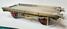
So that's where I've go to. Next the wooden floor and the 'chocks' that sit across the wagon between the sides and restrain the load. Here's a couple more views:


And finally for now, a review of some of the free extra materials and components provided in the kit that you don't need for this build but which might be useful for something else:

Actually, to be fair, some of these are things that are serviceable but I chose not to use - the cast buffer guides and chocks, and the brass cast buffer heads and couplings.
Nick.
)")


")
