HO Castell-y-Bwrdd

introduction

RichardG

Western Thunderer
That would be great to see, especially a track plan to get an idea of what you did. We love a good set of photos on WT!
Cheers
Tony

Castell y Bwrdd is a compact, 1:87 scale model of an imaginary tourist railway which I built during the autumn and winter 2011-2012. The layout has been essentially complete but dormant since then and I think some photos of the build are worth sharing.

plan_for_viewers.jpg

This is "British H0e" running primarily Austrian stock in the style of the Welshpool and Llanfair Light Railway, though supposedly located on the Shropshire side of the border.

The name was inspired by 'Castell y Bere', which I visited with my parents on family holidays in the 1970s, and was encouraged by the existence of Welsh place names like Porth y Waen on the English side of the border. There is also an aesthetic appeal of words written with Welsh vowels and no English ones.

1.jpg
12th November 2011.
There is a vague double meaning in that the real hill at Castell y Bere has a flat top like a table, and the layout is built on a table.

DSCF6641.jpg
The main design requirement was to build a workable model railway able to fit into the boot of my MX-5 in one piece without hinged sections or add-ons. The scale was established by having a pair of HOe coaches to hand, and a desire to build a British model to 1:87 (HO) scale. The baseboard is a plastic hobby table, topped off with a slab of extruded polystyrene sold at the time as loft insulation and commonly known as XPS. The layout is signalled for defined movements, with mechanical control of the points and turntable.
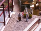
DSCF6948.jpg

DSCF6998.jpg

DSCF6994.jpg
30th April 2012.
The lever frame is a Modratec one with mechanical interlocking, hidden behind the tree.

The idea now is to post a few photos at a time with pauses to let people reply.
 

76043

Western Thunderer
Thanks for posting this Richard, looks a great little layout, which prompt me to ask what size is it? A rough guess a 3' x 2'?
Cheers
Tony
 

RichardG

Western Thunderer
what size is it? A rough guess a 3' x 2'?

The layout is smaller than it looks - just 760 mm wide.

There is a sector plate built-in as a sort of intergrated fiddle yard (more on this later), and the depth of the layout is 495 mm minimum (as pictured above) increasing to 597 mm with the sector plate fully extended.

DSCF6706.jpg
There was a set of folding legs which came with the table. These set the rail head about 775 mm above the floor, which was good for sitting down to operate.

The legs wouldn't go in the MX-5 along with the layout, and the whole assembly was always a bit inclined to topple over, so nowadays the layout goes on a table for operating.
 

Simon H

Western Thunderer
It's lovely to see something so imaginative and, well, different! I've modelled in both 009 and H0e for about the last 45 years, but until recently hadn't seen a British outline H0e layout (I do know of another in progress).
It makes a lot of sense, as there's plenty of applicable figures, scenic elements and vehicles as well as the rolling stock.
Following with interest!
Simon.
 

76043

Western Thunderer
Keep going please Richard, some rolling stock pics might be good, along with some more detail shots of the buildings.
Cheers
Tony
 

RichardG

Western Thunderer
Yes it should be a relief to organise a layout thread by subject instead of as a sequence of activites.

Most of the stock is RTR. After the layout was built I got a contract away from home, and when I returned I thought about new projects. I need to take some fresh photos of the stock.

I do have plenty of photos from the construction but I need to sort through them. This was before I had either a macro lens or a studio flash head! The topics I can post about "now" include the lever frame, turntable, track laying, sector plate, scenic treatments and buildings.

Here are some photos of the progress during the first four months to give an overview of the project while I organise myself . . .

DSCF4469.jpg
14th November 2011
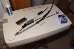
A mock-up before buying too many kits and parts.
Frosties = ruined castle; white board cleaner = folly; lid of plastic tub = turntable; tape measure = tree (since moved).

DSCF4613.jpg
2nd December 2011
I have built the lever frame, and the Hornby wayside halt building has been lopped down vertically for H0, improving its proportions in the process

DSCF4726.jpg
20th December 2011
A final check on clearances before track laying

DSCF5389.jpg
13th January 2012
The track is now layed …

DSCF5540.jpg
18th January 2012
… and the landscape is carved into shape.
The electrical switches are tucked in underneath the plywood holding the sector plate, so there is nothing sticking out from the sides of the model.

DSCF5623.jpg
29th January 2012
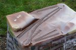
Painting the track.

DSCF6354.jpg
27th March 2012
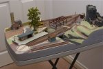
Jumping ahead about eight weeks, I have most of the layout built with the basic scenery in place.

I have loads of photos of subassemblies and scenic details so I can write about these one at a time and it should now be fairly clear where they fit in. Perhaps do the buildings next?
 
sector plate

76043

Western Thunderer
Thanks Richard, the sector plate, I don't quite get what's going on there as it doesn't appear to be present, or maybe it's designed to be an abandoned sector plate? Any chance of further information please?

Looking forward to trackwork info too...
Tony
 

RichardG

Western Thunderer
Well, the sector plate is now abandoned but not for the reason I intended.

The idea was, to include a section of "moving ground" on the model. This would serve as a minimal fiddle yard to allow self-contained operation, and could be posed "closed" to let me connect an extension which I never built.

DSCF6187.jpg
Closed for running onto an extension, with the point giving access to the workshop building.

DSCF6186.jpg
Opened to give access to the first storage road.

DSCF6192.jpg
Opened to give access to the second storage road.

Fairly obviously, the sector plate carries its own point lever, this is a length of brass tube glued onto a toggle switch to connect the power the frog.

The two storage roads are modelled as abandoned tracks so they don't look out of place when the sector plate is closed.

After a while, the sector plate warped just enough to make it jam up, so it isn't very usable nowadays. Maybe I should build that extension!
 

RichardG

Western Thunderer
Steel balls - two of them.

DSCF6161.jpg
The ball seen here supports the plate when a train runs across the edge of it.
A second ball goes in the cavity to the left and provides a rudimentary indexing mechanism.

DSCF6176.jpg
There is a machine screw with a compression spring to set the pressure on the indexing ball.

DSCF6158.jpg
Like this.

DSCF6170.jpg
The indexing ball engages with four rebates arranged in an arc underneath. Here are the first two I made out of steel washers.

I ended up with two steel washers and two pop rivets as the rebates. The heads of the pop rivets give a shallower drop so a softer latching mechanism.
 

RichardG

Western Thunderer
It's lovely to see something so imaginative and, well, different! I've modelled in both 009 and H0e for about the last 45 years, but until recently hadn't seen a British outline H0e layout (I do know of another in progress).
It makes a lot of sense, as there's plenty of applicable figures, scenic elements and vehicles as well as the rolling stock.
Following with interest!
Simon.
Thank you Simon for your kind comments. The layout is an attempt to get away from the "boxed in" look of some micros. With no backscene the model is easier to build, has more viewing angles, gives more viewers a better look, and the operator can engage better with viewers. The layout was popular with parents asking about possibilites for a layout for their children.

Looking forward to trackwork info too...
To be honest, the tracklaying was a bit of a non-event. It is all commercial points and flexi-track and there is nothing I have made myself except for the turntable.

Installing the sector plate meant fixing down the slab of XPS so I think it is best to post a few photos of these, wait a wee while for any responses and then do the turntable.

DSCF4910.jpg
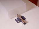
There is a storage box slid under the hill with the castle, and the very first thing I fixed down onto the baseboard was a cupboard door opener to let me take the box out. There are a lot of pop rivets in this build, to fix things onto the plastic table top.

DSCF4921.jpg
The second thing to fix onto the table top was a switch for whatever lighting circuits and scenic effects I put on the model. This is fixed straight onto the table top without a back box, and its terminals are accessible underneath.

Then I glued down the slab of XPS. The 'No More Nails' was the wrong choice. It never set properly (neither surface is porous) but 13 years on it has dried out so much now I guess everything is held together by stiction. Memory is hazy but I think there are a few long self-tapping screws holding the XPS onto the table, to keep it flat while the glue tried to set. I have forgotten where these screws are.

DSCF4930.jpg
The area for the sector plate and its two sidings.

DSCF4804.jpg
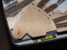
There are three layers of plywood for the base, and one layer for the plate itself. If a sector plate is going to be this thin it ought to be cut from something like aluminium which cannot warp.

DSCF4873.jpg
The plywood base is braced with stripwood and there is a hole cut for an inspection pit.

DSCF6409.jpg
With the plyywood base glued down onto the XPS, the power feed for the sector plate goes through the pivot . . .

DSCF6207.jpg
. . . and all the way down to the underneath of the table.
 

RichardG

Western Thunderer
Keep going please Richard, some rolling stock pics might be good, along with some more detail shots of the buildings.
DSC_0078.jpeg
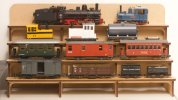
Castell-y-Bwrdd is from a time when I had a different take on my hobby; I was buying my model trains ready-made and most of my constructive effort was in the layout. This is my entire collection of trains for the layout.

The white diesel loco is a brass body kit on an N-gauge Plymouth diesel, and the tank wagon is Tri-ang TT on a Lima N-gauge chassis. The other models are much as their factories made them. I see the Roco 0-8+4 as a visitor, it is quite an incredible model and very different to the other locos. I doubt an example has ever come to the UK.

The business of running trains is made difficult by me adding miniature knuckle couplers to some of the stock but not all of it. The locos get a test run from time to time and they still run well; the layout is asleep.

The display stand is from Tim Horn at the Stowmarket MRC show earlier today.
 
turntable

RichardG

Western Thunderer
The turntable operates as a sector plate (about 23 degrees of movement) and lets a locomotive run round its train.

101.jpg
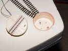
This is still my only attempt at making a turntable. I have always fought shy of trying because of the difficulty of locating a central spindle at the exact centre. Looking at a tub of hand cream with a screw lid, I realised I did not need a central spindle at all.

My model uses the screw thread of the lid to support the table; this allows easy dismantling if needed for servicing. It also limits the functionality of the model to that of a sector plate; and the relatively coarse pitch of the thread provides about only a quarter turn of usable movement.

102.jpg
The first step was to take the tub of hand cream, transfer the contents to another container and then wash out the tub and peel off the labels. Then I attached a length of track to the lid. Both the lid and the Peco sleeper base are grades of polyethylene, invariably difficult to stick. I spread UHU All Purpose Adhesive on both the lid and the sleepers and waited for it to dry, and then made the bond with a third layer of the same glue. I also put in four pins, one at each corner of the outermost sleepers. These are secured by bending them across under the lid.

The decking is from matchsticks glued to pieces of 1 mm plywood.

103.jpg
I added two self-adhesive paper labels to the lid to make foundations for the decking. Then I glued the plywood holding the matchsticks onto the paper labels.

104.jpg
The underside of the tub is reinforced with a piece of 1 mm plywood (not visible here), attached with two pop rivets.

The lid and the tub use a triple-start thread. I rotated the base with respect to the lid to set the correct height, and then glued the plywood base to some strips of wood fixed to the tabletop.

105.jpg
The tub sits within the XPS foam but isn’t fixed to it.

106.jpgWhen I knew the turntable would work, I filled in the spaces outside and between the rails with more 1 mm plywood.

107.jpg
Electric wiring for the track on the turntable.

108.jpg
Early test runs showed me I wanted some kind of remote control. I installed the simplest arrangement I could think of, which is a length of piano wire to push and pull the periphery of the lid of the tub. I can detach the wire from the lid to let me dismantle the turntable for maintenance, but I have not yet needed to do this.

109.jpg
I finished the turntable with a ring of 'paving slabs' cut from styrene. These are cemented onto packing pieces of styrene, glued onto the XPS to bring the slabs up to reach the height of the decking.
 

paulc

Western Thunderer
The turntable operates as a sector plate (about 23 degrees of movement) and lets a locomotive run round its train.

View attachment 243307
This is still my only attempt at making a turntable. I have always fought shy of trying because of the difficulty of locating a central spindle at the exact centre. Looking at a tub of hand cream with a screw lid, I realised I did not need a central spindle at all.

My model uses the screw thread of the lid to support the table; this allows easy dismantling if needed for servicing. It also limits the functionality of the model to that of a sector plate; and the relatively coarse pitch of the thread provides about only a quarter turn of usable movement.

View attachment 243308
The first step was to take the tub of hand cream, transfer the contents to another container and then wash out the tub and peel off the labels. Then I attached a length of track to the lid. Both the lid and the Peco sleeper base are grades of polyethylene, invariably difficult to stick. I spread UHU All Purpose Adhesive on both the lid and the sleepers and waited for it to dry, and then made the bond with a third layer of the same glue. I also put in four pins, one at each corner of the outermost sleepers. These are secured by bending them across under the lid.

The decking is from matchsticks glued to pieces of 1 mm plywood.

View attachment 243309
I added two self-adhesive paper labels to the lid to make foundations for the decking. Then I glued the plywood holding the matchsticks onto the paper labels.

View attachment 243310
The underside of the tub is reinforced with a piece of 1 mm plywood (not visible here), attached with two pop rivets.

The lid and the tub use a triple-start thread. I rotated the base with respect to the lid to set the correct height, and then glued the plywood base to some strips of wood fixed to the tabletop.

View attachment 243311
The tub sits within the XPS foam but isn’t fixed to it.

View attachment 243312When I knew the turntable would work, I filled in the spaces outside and between the rails with more 1 mm plywood.

View attachment 243313
Electric wiring for the track on the turntable.

View attachment 243314
Early test runs showed me I wanted some kind of remote control. I installed the simplest arrangement I could think of, which is a length of piano wire to push and pull the periphery of the lid of the tub. I can detach the wire from the lid to let me dismantle the turntable for maintenance, but I have not yet needed to do this.

View attachment 243315
I finished the turntable with a ring of 'paving slabs' cut from styrene. These are cemented onto packing pieces of styrene, glued onto the XPS to bring the slabs up to reach the height of the decking.
Cor , thats so simple but looks like it works a treat . Well done Richard .
Now , i was thinking about a wagon turntable ..........
 

RichardG

Western Thunderer
Now , i was thinking about a wagon turntable ..........

This sort of tub is designed to let you twist the lid off and back on again very easily; and so the thread is a triple-start one. I have got away with this here because the lid rotates only about 23 degrees between the two tracks. In the process, the lid goes up and down about 0.2 mm. It was easy to fix the tracks at slightly different heights.

For a wagon turntable where we want 90 degrees of movement, I would try shaving off the thread on the tub so the remains of the thread provide a bearing surface for the thread on the inside of the lid. So the turntable doesn't go up and down.
 

simond

Western Thunderer
I think I’d use a piece of PCB, cut to a circle, and solder the rails on. It would be necessary to provide insulating gaps only if it would have locos on it, which would be pretty unusual I think.
Could go mad and provide bearings but I guess some slippery plastic sheet on the baseboard would be sufficient, with a central pivot.
The deck could be balsa.
 

RichardG

Western Thunderer
The tub of cream has the advantage of not needing a central pivot, which can be quite tricky to get dead centre.

Incidentally for 7mm I believe people have used a CD with the insert of its case (as the pivot) to make the basis of a wagon turntable.
 

RichardG

Western Thunderer
start with the pivot and work outwards!

Simon I agree, but using the tub of cream means the whole circumference of the turntable is supported. Also the flange around the edge of the lid discourages warping. This is more important to me than having a central pivot, which has no practical benefit when the deck only needs to rotate through 20-odd degrees. The tub did work out okay, and it still works 13 years on.
 
Top