HEAVY METAL Gallimaufry

Riveting experience - 'gangnam style'
  • Brian McKenzie

    Western Thunderer
    Something I've wanted to try is to equip a CNC milling machine for embossing rivet heads.

    The first version was a spring-loaded tool fitted directly into the machine spindle, but the spring used was far too feeble to make any impression. Being mindful of applying shock loads to the spindle bearings, a more complex arrangement of turnings was assembled to transmit the minor impacts straight into the machine body, avoiding the spindle. This unit is held in position by the air-operated fingers that grip the 'pull-stud' that is screwed into the upper end of regular tool holders or chucks.
    IMG_87011_Rivet punch.jpg


    Bogie Sideframe.jpg

    Although a die plate was made for the bogie sideframe example in the video below, the concept works sufficiently well to be worth devising a single fixed female die - and using the CNC motion to feed the sheet metal over it - thus obtaining rivet patterns quickly off any digital plan.
     
    Last edited:
    Joggling brass angle
  • Brian McKenzie

    Western Thunderer
    Currently scratchbuilding a few wagons originally of British design for New Zealand Railways. 9mm scale is used for O gauge track, which scales neatly for 3' 6" gauge.

    Machining all the many different size angles used by the prototype became tedious. But interest perked up by tinkering with a tool to see if a joggled end could be formed in angle with a wall thickness of 12 thou (0.3mm). Photo shows the first piece made and installed.

    IMG_9481+ joggled angle_1.jpg

    Then when I inserted the prototype pic above, noticed the end treatment of an angle along the top edge was not the same as for the wagon's other less tidy end - which I had copied.

    IMG_8462a Joggled angle.jpg


    IMG_9450a Joggle die block.jpg


    IMG_9434a Joggle tool for 1.5mm angle.jpg
     
    Boring wheels for 2mm dia axles
  • Brian McKenzie

    Western Thunderer
    This unusual method was used to finish bore axles holes in a recent batch of tiny drivers for industrial locos.
    It's more model engineering based than model-making, but may be of interest to some.

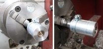
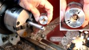
    For larger diameter wheels, it has been practical to secure them with screws into the end of a bar in the lathe - and 'clock' them up with a dial indicator to run true. This time the small size precluded that, so an alternative method was devised to hold them. This is basically a long oversized collar arranged to clamp the wheel from the outer front face of the tyre, against the end of a mandrel.

    Boring arrgt for 2mm axles.jpg

    An important requirement is that it is necessary that the OD of all wheel flanges is identical, and that this diameter can be reproduced successfully in the two aluminium items used to mount the wheels.
    Boring 2mm dia axle holes.jpg

    The clamp component is made first, bored very carefully full length, that can accept the wheels over the flange diameter with no axial play.
    It is easier to bore this right through to achieve the diameter required, then insert a stubby bush in the opening to retain the wheel.

    A mandrel is then turned to be a very neat fit inside the large collar. The length of these components can be judged from the photos.
    The collar is made long enough to have several saw cuts across the end nearest the chuck, and a hose clamp is used to tighten this to the mandrel. Some sideways pressure applied by hand when tightening the hose clamp is quite sufficient to drive for the drilling and boring operations.

    -Brian McK.
     
    Top