Highbridge and Dartmouth

Paul Townsend

Active Member
I am starting a new workbench thread to continue the introductory messages in my thread as a "new member".

Having started here in 2012, now some 11 years later I reckon I am no longer "NEW".
I trust moderators will agree.

Both my layouts include some features which were new at the time although many of those applied in Highbridge are used by many other bods and I don't often claim to be the originator as the construction has been spread over 42 years and counting.

Dartmouth, being younger, at a mere 5 years preceded by 5 years of preparations, has more uncommon and sometimes innovative features some of which actually work properly !
 
Last edited:

Paul Townsend

Active Member
I am starting a new workbench thread to continue the introductory messages in my thread as a "new member".

Having started here in 2012, now some 11 years later I reckon I am no longer "NEW".
I trust moderators will agree.

Both my layouts include some features which were new at the time although many of those applied in Highbridge are used by many other bods and I don't often claim to be the originator as the construction has been spread over 42 years and counting.

Dartmouth, being younger, at a mere 5 years preceded by 5 years of preparations, has more uncommon and sometimes innovative features some of which actually work properly !
The current project is planning the MkIII led overhead lighting for Highbridge. I refered to the inadequacies of MkI and MkII recently in my "New Member " thread.
MkIII comprises latest best available high power led strips on self adhesive backing attached to 50 x 50 mm angle alloy. This provides mechanical support, heat dissipation and eye line obstruction to avoid dazzle.
A trial has been very successful so I need to arrange permanent support for the long alloy angles. Trial used 3 of 2.7M runs liberated from another project, suspended by string. The exact locations and height are being chosen to give even lighting at high brightness.

Mk I and MkII used 12v ac but MkIII requires 24v DC at 1.1Amp/Metre run. Fortunately I had 4 old 12v DC 4Amp supplies for the trial arranged as series pairs. The final version may well run to 15-20M so up to 22Amps required . For my Dartmouth similar rig all strip pelmets carry 3 runs of 12v leds in series so a 36v DC supply was purchased, giving about 8 Amps.
Mr Ohm declared that the desired 24v at leds needs some 26v from the PSU or fatter wire. Quite how I will address the PSU's and wiring in the final rig is not yet known.......
 

Paul Townsend

Active Member
Here are a few pictures of Highbridge
 

Attachments

  • Corner shop WA P1070638.jpg
    Corner shop WA P1070638.jpg
    47 KB · Views: 74
  • P1030795.jpg
    P1030795.jpg
    151.3 KB · Views: 74
  • image2.jpeg
    image2.jpeg
    27.4 KB · Views: 73
  • Highbridge Track Plan annotated.pdf
    1.1 MB · Views: 16
  • LEDs under MPD.JPG
    LEDs under MPD.JPG
    164.9 KB · Views: 70
  • 20150929_190024_2.jpg
    20150929_190024_2.jpg
    244.6 KB · Views: 71

Paul Townsend

Active Member
and a few pictures of Dartmouth
 

Attachments

  • P1080387.JPG
    P1080387.JPG
    194.9 KB · Views: 100
  • P1080363.JPG
    P1080363.JPG
    218.8 KB · Views: 89
  • P1080354.JPG
    P1080354.JPG
    275.2 KB · Views: 88
  • P1080456.JPG
    P1080456.JPG
    83.4 KB · Views: 86
  • P1080481.JPG
    P1080481.JPG
    235.3 KB · Views: 89
  • Olton Bridge.jpg
    Olton Bridge.jpg
    153.8 KB · Views: 89
  • P1030202.JPG
    P1030202.JPG
    145.1 KB · Views: 100
  • P1040118.JPG
    P1040118.JPG
    173.3 KB · Views: 98
  • FYCP general tests -P1070636.jpg
    FYCP general tests -P1070636.jpg
    117.1 KB · Views: 99
  • P1080544.JPG
    P1080544.JPG
    130.2 KB · Views: 99
  • P1070662.jpg
    P1070662.jpg
    283.7 KB · Views: 102

AJC

Western Thunderer
Hello Paul - I look forward to seeing (and reading) more about these two projects. Is there any chance that you could upload images in full size rather than as thumbnails? If you use the 'Upload Files' box, then a click on 'insert' will give the option of 'full', and that's clearer all round.

Adam
 

Paul Townsend

Active Member
OK will do. I will repost the bunch of bigger piccies in my original Newbie thread as they are historic, not really workbench topics.

I am very familiar with Fora using phpBB but have to learn a few tricks for this one:headbang:
 
  • Like
Reactions: AJC

Paul Townsend

Active Member
In the next hour or two I will post the bigger versions of these Dartmouth piccies in my original Newbie thread.
Later on I will do likewise with the Highbridge thumbnails.
 

Paul Townsend

Active Member
Some notes on recent projects with overhead LED lighting. c. 2015- date.

Highbridge had overhead 12v QI floods and spots when newish. A chum suffered from eye irritation and the heat was sometimes excessive so as soon as 12v MR12 LED dropin replacements became useable and affordable I changed to those. Early ones, c. 2000 were a bit too dim but we were cooler and his eyes were happier.
In 2016 we moved HB to its new home in a shed and brought the same lighting although the supports were rebuilt due to different ceiling material and height. A growing perception was that the lighting was rather patchy so additional leds were rigged. However the low height of the rig is pretty unsightly and light is still too patchy.

The development of Dartmouth for exhibiting required application of the best current techniques as seen at shows with LED strip lights between 2015 and 2020. I was attracted to this system as:
1. Supports can be thinner and lighter than other illumination sources.
2. LV only overhead so intrinsically safe, 12v - 36v DC instead of 240v ac.
3. Even illumination that can be dimmed and/or controlled for colour temperature.
4. Steadily increasing brightness and falling prices of this rapidly evolving technology in years 2017 - 2022

I have now finished the Dartmouth rig. It comprises :
1. just 4 gallows supports over the 8.2M length, fabricated from 25mm square steel Speedframe
2. 3 x 2.75M lengths of angle alloy 50 x 50 x 3 mm to give strength, this gauge was chosen to meet my calculated maximum sag of a few mm in each unsupported length. Such calculations of beam design are easy for an engineer.
3. Ditto lengths of white PVC angle which nestle inside the alloy allowing best reflection and control of angle of the light beams from individual PSU output.
4. 3 runs of 2.75M self adhesive 5050 LED strips. Each run contains 3 strips of leds, 2 warm white and one cool white giving a good colour balance and enough brightness to allow dimming if wanted. The height of the strips above the baseboards is 700mm and the boards are only 600mm wide. The result is even, shadow free illumination at 3000 Lumen/Metre which does not dazzle the viewer, just reaches the backsceme and looks great.
5. Power supply to provide nominal 36v at 10 Amps, actually set to about 37.2v to allow for voltage drop in the wiring.
6. Wiring is in three runs to the 3 alloy girders, connectors are 4pin XLR at both ends. The PSU sits on the floor near layout centre so middle run uses 4M of 6 wires of 16/.2 mm. The outer 2 runs are 8M of 6 x 1.5mm. This ensures minimal voltage drop and full voltage arriving at LED strips.
The 6 wires allow individual feeds to each strip and they are arranged in series/parallel so that e.g. all 3 CW runs are in series and fed from an individual PSU output. The commercial 36v 10A PSU is enclosed in my own steel box for strength and safety. It feeds 3 x FETs to allow for 3 dimmers to be driven either manually or computer controlled by Arduino to give day/night effects of changing brightness and colour temperature.

Offcuts of the LED strips are mounted on a 0.5mm wood strip to illuminate the workbench in the same way as the layout. This meets the ideal specification to paint buildings under the same lighting as the display model.

I am very pleased with the result since it was completed in 2021. Its worth noting that since I bought the LEDs in 2017 which have CRI > 90%, those available in 2022 are now brighter and have better quoted CRI of 95%.
Do NOT buy cheap led strips from Ebay etc if you want predictable results. Going to a decent professional supplier provides quality backed up by data sheets. ( LED Hut and Downlights Direct gave me good service)

Piggy backing on the success of the Dartmouth illuminations we are now upgrading Highbridge's lighting. The project is ongoing and will be finished within a few weeks. The new 5730 LED strips use latest version available: Cool white 5050 24v strips giving 3050 Lumens/M from 26Watts/M.

Each run is mounted directly to 50 x 50 x 3 mm alloy angle in runs of 3 or 4M This provides the required heat sinking which was not an issue in the Dartmouth rig. The alloy girders are near ceiling height and the bright and even illumination outperfoms the spotty earlier version in spades.

Soon I will dismantle the old led spots and the aesthetic appearance will gain greatly. Also the tallest visitors will avoid scorches on their bald patches! As HB is long since painted I had some concern about the layout's appearance under new lights with more brightness and a different colour temperature albeit with better CRI. Trial was promising and the 2/3 area completed looks good. 4 runs up, 2 to do.
The wiring is simpler than Dartmouth as I have no need of, or way of, varying colour temperature. I could easily add dimming later if wanted.

I used the same Amazon Chinese PSU as Dartmouth but in 24v guise. There are 2 of these allowing up to 20Amps total, not quite all needed.

One needs to recognise that bright lighting produces heat, even the modern very efficient leds.
Dartmouth has 360w of power for something like 10 times the lumens compared to old tungsten filament or QI bulbs of our youth.
Highbridge's new lights will need a bit below 480 watts. It helps to heat the room in winter and the air-con deals with this in summer.
 
Last edited:
Dartmouth Backscene

Paul Townsend

Active Member
Dave gave me enough sky to cover the entire wall behind Dartmouth. The longer roll is now jury rigged to see the benefit. It can shuffle right to curve around the corner and then the other bit will extend past the fiddleyard.

Olton Bridge is removed temporarily for safety while rigging the backdrop. It will stay out for a few jobs to be done on it:
Solving a failed dropper wire, laying the narrow gauge line to Plymouth (South Hams Rly Co.) which passes below the bridge, improving the grass which has bald patches etc.

The overhead led strip lights are not on in these pix. I need to assess glare from the shiny sky before showing those.
The left end (1st Piccy) is the station terminus and is currently cluttered with rolling stock to avoid accidemnts while rigging the sky.

Lots of Merg electronics is exposed, when fully debugged it will all be hidden.
The half-chair gluing down is near finished so onto rail painting soon and then ballasting.
1_Left_IMG_2454.jpg2_Centre_IMG_2455.jpg3_Right_IMG_2456.jpg
 

Paul Townsend

Active Member
I put on the led strip lighting and as expected there is a lot of flare on this backscene which is very unhelpful.

That is why Dave ditched it and replaced his with a matt finish.

While I don't rule out the expenditure on a new one without gloss I am not keen as this backscene is just interim until I find the roundtuit marked
" do it Paul Bambrick's way". I did his Missenden course pre-Covid and have seen the results of his 3D backscenes at exhibitions and so I know it is the only long term option for me. I have a 1/2 metre sample made at Missenden and it continues to inspire me and be admired by chums. I also have the book.

Meanwhile I have in mind to attempt to spray this glossy job with a matt varnish.

I have experience of doing this on locos etc but never on 5 sq Metres!

Advice please on best varnish to use and how to apply it.
 

ullypug

Western Thunderer
Paul
Halfords do a rattle can of Matt lacqer for £8. I’ve not used it but I would have thought it a better bet for larger areas.
I like the dexion speedframe idea. Any noticeable sag on the cantilevered arm? I’m starting to think about the lighting rig for Cheddar.
 

Paul Townsend

Active Member
Paul
Halfords do a rattle can of Matt lacqer for £8. I’ve not used it but I would have thought it a better bet for larger areas.
I like the dexion speedframe idea. Any noticeable sag on the cantilevered arm? I’m starting to think about the lighting rig for Cheddar.
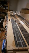
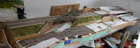
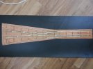
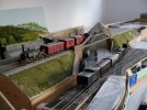
The led supports are 50 x 25 x 3mm alloy in 3 runs of 2.75M. This gauge chosen to give the required beam stiffnes so that the distributed load and the four gallows supports cause a maximum deflection of so few mm that the eye doesn't notice it at all. The spans between the supporting gallows vary but the longest is 2.7M and the beam calculations allow for that. The 4 gallows locations coincideT with 4 of the 6 steel trestles that carry the layout. Again beam calculations told me that the spans between trestles won't allow the baseboards to sag.

The load included on the overhead alloy beams is a PVC 40 x 40 x 2 inner angle cunningly arranged to pivot and carry the leds. Thus the 50mm alloy face is vertical but the inner PVC carrying the leds can be tweaked to give best angle for illumination.

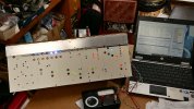
I use 3 led strips per section to give the CRI and colour temperature required. The led strips I used are rated at 72 Watts/M and each 2.75m run of 3 strips deliver 3000 Lumen/M. They are 650mm above baseboards which are 1300mm above the floor.
These heights ensure that smaller viewers need hop-up stools and don't rush about, tall viewers are less likely to bonk the overheadf rig, and I get baseboards at a good level for operating as well as construction. The sight lines to the backscene are to my liking also.
The temperature rise of the leds is 18degC after 30 mins so will be fine all day. Note that users of the latest higher power LED strips need to mount them directly to the alloy support to provide heat sinking as they consume nearly double the Watts/M producing most of that as heat.

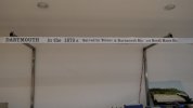
NB I used these on Highbridge's new rig where the alloy beams are 50 x 50 x 3mm and hung so the angle edge is on top so both faces are 45 deg off vertical. Lenghts are 3 and 4M. This being a permanent rig, no nice vertical face is required for labels etc.

Now to Andrews question.
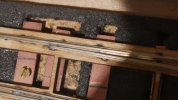
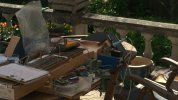
The gallows and their load have been erected for over a year and I just put my set square to the rear top right angle joints.
3 are pretty much still square, bear in mind that my horizontals are only 640mm. Wider baseboards would require more length here.
The worst sags by less than 18mm. It looks as if I haven't quite driven the joint home so that may improve after a visit from the mallet. Obviously safety consideration at a show requires certainty and one can easily add triangle plates to reinforce those joints.
Speedframe joints come in 2 flavours, permanent and dismantleable. I used the former as the gallows are small enough to travel as rigged.
I suspect that sag at those joints would increase with wear of the latter type.
 
Last edited:

Paul Townsend

Active Member
Thanks to Andrews recommendation to use the Halfords matt lacquer on the glossy sky backscene.
Dave helped me yesterday to take it down and spray it in the open air, smelly stuff!

Replaced it behind the layout and a great improvement. Two light coats on the approx 5.5M x 0.6M roll required 2 cans of 300mL costing £16 + petrol to get to a Halfords.

It was less than 2 hours work and very good value for time and dosh.

As I took the only 2 cans in stock there will be a delay before acquiring 2 more cans to do the other roll of c 2.6M.

We took advantage of the re-rigging of the sky to move it left by 1.2M thus generating a bit to form a curved corner.
 

Paul Townsend

Active Member
Halfords matt lacquer is in short supply. I had to go to Malvern to collect 2 pre-ordered cans.
At home discovered they had sold me 1 matt and 1 satin....Grrr.
I might just have enough to do the last 3M of Dartmouth sky when weather is a bit drier.

Meanwhile, as Olton Bridge baseboard is out for safety while doing the sky backscene I have been rectifying wiring faults.
AS built 20 + years ago by the late Mike Jolly it had too few dropper wires so short lenghts of rail; were unconnected.

I have added 34!

It was a hard job as the baseboard has a false floor some 100mm below the track bed so to get thin wires through I acquired some 150 x 2mm drills.
Even then fishing the wires down the bottom hole was challenging so I opened them up to 25mm. Use of torch and a stiff wire hook worked slowly.
Here is a piccy of the underside now the wiring is tested and OKOlton Bridge underside_IMG_2459.jpgNext job is to lay the narrow gauge track to Plymouth which goes under the bridge.
 
Top