daifly
Western Thunderer
In answer to your query Barry, the thread is here:
Cheers
Dave
Cheers
Dave
Last edited:
Yes that’s them, just be a little careful with soldering near to them.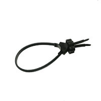
Flexible strap clamp
Flexible strap clamp, ingenious design, ideal for clamping fingerboards plus many other useswww.touchstonetonewoods.co.uk
Dave


 [/url]
 [/url]
 [/url]
 [/url]
 [/url]
 [/url]
 [/url]
Very clever profiling for the lamp irons - I'm assuming you started with a thicker sheet of n/s for the footplate and skimmed virtually the whole sheet - leaving the raised "dog-bones" for the lamp irons.The front running contains a lot of details, some quite distinctive.
Most of the bits had already been made, but the guard irons hadn’t. These required some interesting machining once the basic shape had been cut out on the profile miller. Holding parts for machining is always challenging, as sometimes the parts can be marked if held in a vice, so to machine the front face to the correct depth, and add the small lip on the bottom I soldered them to some brass plate. Care is needed with the cuts, so lightly does it and with a new sharp cutter, no problems were encountered, the same technique was used on the back face to reduce the thickness for the mounting onto the buffer beam.
That’s most of it completed, with just the buffers, oiling pots , couplings and add a few bolt head details to do.
Simon
View attachment 253072[/url]
View attachment 253073[/url]
View attachment 253074[/url]
View attachment 253075[/url]
View attachment 253076[/url]
View attachment 253077[/url]
View attachment 253078[/url]
Thanks Adrian,Very clever profiling for the lamp irons - I'm assuming you started with a thicker sheet of n/s for the footplate and skimmed virtually the whole sheet - leaving the raised "dog-bones" for the lamp irons.


