Rob Pulham
Western Thunderer
Although these parts are allied to the Princess build, I thought that I would add the making of them and the reasoning behind it as a separate thread just in case anyone has need to solve a similar problem in the future.
Readers of the David Andrews Princess thread will have noted that I had to make the brake gear removable to ensure that I could remove the wheels due to them being mounted on telescopic axles. This need stems from a similar issue but I will start at the beginning.
Although the gent that I am building it for doesn't want full inside motion. One thing that is quite visible through holes in the front frames, is movement of the crossheads. I was asked if I could add some element of movement using the spare outside motion bits from the kit ( a set of Premier rods etc. has been supplied for the build). Having started to think about it long before getting to the actual start of the build I realised that with the axles being hollow I couldn't use traditional cranks to make the crossheads move (or rather I wasn't comfortable that I could make it work without ruining axles wheels). So I thought that a pair of eccentrics would impart movement while being able to be attached to the hollow axles without having to cut them.

We agreed this as the way forward and I ultimately bought castings for the slide bars/crossheads and eccentric straps from Laurie Griffin. I was also going to buy some eccentric sheaves too until I recalled Nick Dunhill finding the new cast versions very time consuming to prepare. Further thought made me also realise that the LG cast ones wouldn't really work anyway. This is because in a 'normal' inside motion set up the eccentric sheaves are trapped between the cranks so the eccentric straps cannot slip off the edge of the sheaves. Of course, I planned to use them as a single eccentric so they would need to be restrained at either side.
Instead of ordering a set of cast eccentrics along with the other parts, I bought a length of 12mm round brass bar instead.
Initially I was going to offset in the lathe using a four jaw chuck to offset the bar but having done a bit of research online, most machinists were of the view that you could but if you had a mill it would be far easier to drill it in the mill. Not being as proficient with my mill as I hope to be in time I did use the lathe to put a small centre mark in the end of the bar before transferring it to the vice in the mill.
Then using a centre drill inserted into my centre mark to centre it quickly, it was easy to plot the offset (2.4mm, more on this later) and then drill it out to 4.5mm. I then took it to final size with a reamer.
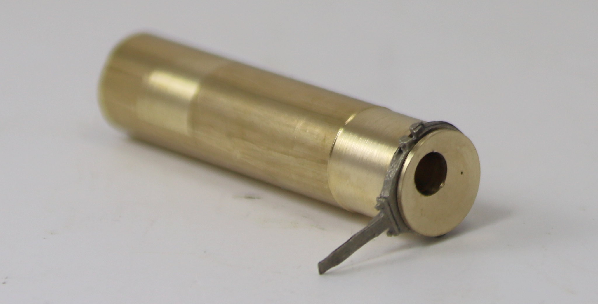
Transferring it back to the lathe I took a skim off the outside and marked up for the first sheave. Some time later we had this.

I tried the eccentric strap for size and found it was just a little too wide for the strap to close completely around the sheave.
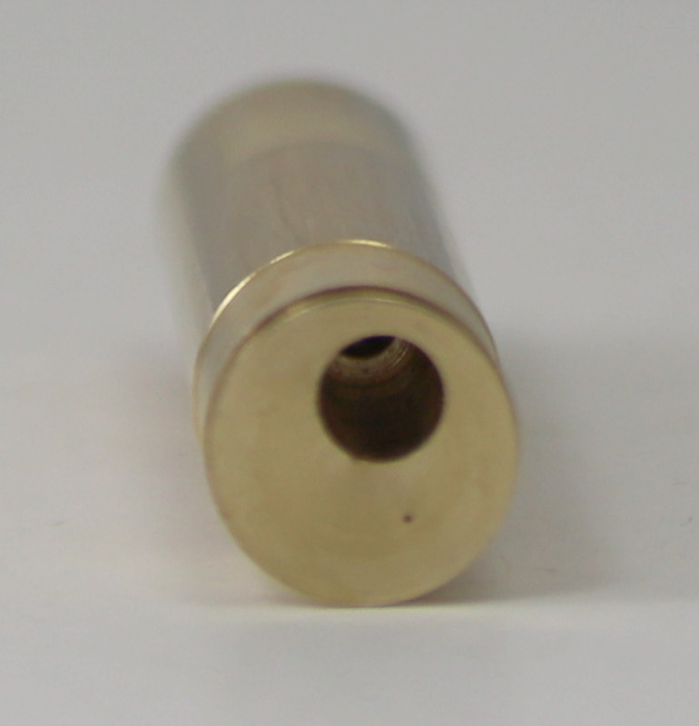
It was at this point that I noticed that the depth of cut of the groove to accommodate the strap was such that it was very close to breaking through into the offset hole. It seems that in setting my offset hole at 2.4mm from the centre to gain the maximum amount of movement was just too much.
You may be able to see the mark where it’s just about to break through in the image below. This was made worse by having to apply a second slightly larger reamer than 3/16 (4.74mm) to get the axle end into the offset hole


The plan is to start again from the other end with a 2mm offset hole and see how I get on.
To be continued…
Readers of the David Andrews Princess thread will have noted that I had to make the brake gear removable to ensure that I could remove the wheels due to them being mounted on telescopic axles. This need stems from a similar issue but I will start at the beginning.
Although the gent that I am building it for doesn't want full inside motion. One thing that is quite visible through holes in the front frames, is movement of the crossheads. I was asked if I could add some element of movement using the spare outside motion bits from the kit ( a set of Premier rods etc. has been supplied for the build). Having started to think about it long before getting to the actual start of the build I realised that with the axles being hollow I couldn't use traditional cranks to make the crossheads move (or rather I wasn't comfortable that I could make it work without ruining axles wheels). So I thought that a pair of eccentrics would impart movement while being able to be attached to the hollow axles without having to cut them.

We agreed this as the way forward and I ultimately bought castings for the slide bars/crossheads and eccentric straps from Laurie Griffin. I was also going to buy some eccentric sheaves too until I recalled Nick Dunhill finding the new cast versions very time consuming to prepare. Further thought made me also realise that the LG cast ones wouldn't really work anyway. This is because in a 'normal' inside motion set up the eccentric sheaves are trapped between the cranks so the eccentric straps cannot slip off the edge of the sheaves. Of course, I planned to use them as a single eccentric so they would need to be restrained at either side.
Instead of ordering a set of cast eccentrics along with the other parts, I bought a length of 12mm round brass bar instead.
Initially I was going to offset in the lathe using a four jaw chuck to offset the bar but having done a bit of research online, most machinists were of the view that you could but if you had a mill it would be far easier to drill it in the mill. Not being as proficient with my mill as I hope to be in time I did use the lathe to put a small centre mark in the end of the bar before transferring it to the vice in the mill.
Then using a centre drill inserted into my centre mark to centre it quickly, it was easy to plot the offset (2.4mm, more on this later) and then drill it out to 4.5mm. I then took it to final size with a reamer.
Transferring it back to the lathe I took a skim off the outside and marked up for the first sheave. Some time later we had this.


I tried the eccentric strap for size and found it was just a little too wide for the strap to close completely around the sheave.

It was at this point that I noticed that the depth of cut of the groove to accommodate the strap was such that it was very close to breaking through into the offset hole. It seems that in setting my offset hole at 2.4mm from the centre to gain the maximum amount of movement was just too much.
You may be able to see the mark where it’s just about to break through in the image below. This was made worse by having to apply a second slightly larger reamer than 3/16 (4.74mm) to get the axle end into the offset hole


The plan is to start again from the other end with a 2mm offset hole and see how I get on.
To be continued…
")


