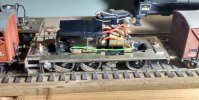
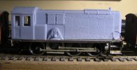
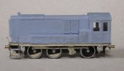
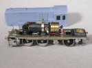
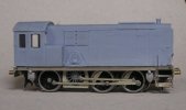
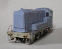
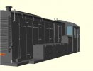
4mm Mercian Models Armstrong Whitworth 0-6-0 Diesel Electric Shunter in EM Gauge

Stevers

Western Thunderer
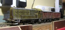
This all came about because I thought we would need a shunter to work a military depot that my son was planning at the time. The depot was on a freelance layout that was set in a real location on the south west corner of Salisbury Plain. I chose this over a nice straightforward Sentinal only because I liked the look of the jackshaft drive that divided the coupled wheels. My kit was purchased at the NEC in about 2006 from the ever helpful Trevor Cousens, who agreed to send me a second chassis etch so that I could fully articulate the coupling rods. This with a view to compensating the chassis on the Sharman principle, and yes, I did contemplate driving the jackshaft, but not for very long! I was sorry to find out somewhat belatedly that Trevor had passed away as I enjoyed my chats with him at exhibitions.
P2140503.JPG
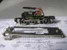
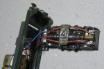
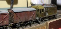
The chassis was built up with High Level hornblocks and gear box, a Mashima can motor and a biggish flywheel. The driven axle is fixed and there's a single beam supporting the compensated axles each side of the jackshaft. The flycrank(?) was laminated up from nickel silver sheet so that I could set the throw to match the wheels which were intended for a J94 Austerity Tank. Opposite the flycrank I used a loco wheel without the steel rim, as those provided in the kit were spoked though clearly the wrong size - more of that anon. I now know that this wheel should not be spoked, and I will fill the spokes in with Milliput when I do the other changes that will be required. Once I'd given the centre driven wheel enough sideplay it has proved to be an excellent runner on curves down to 3' radius. I didn't make the greatest job of building the etched brass body but I think it would have been OK once filled and painted. If I was doing it again I'd definitely scribe the corners of the cab before bending them.
P2140496.JPG
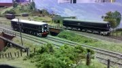
So, to the scale of my problem... With the body fitted it became apparent that it towered over any box van put next to it, so I checked the Roche drawing and realised that the model was in the order of 4mm too high, 2mm too wide and 2.5mm too long. The Roche drawing may have its limitations, but I'd like to think the written dimensions are correct!

Prototype4mm Scale (mm)Mercian Model (mm)
Height to top of cab12'6"5053.75
Width of cab8'5"33.66736
Length of running plate28'0"112114.5

At that point in my modelling career it hadn't occured to me that an etched kit of this nature could be quite so far out. My understanding had been that the kit for this English prototype was derived from an H0 kit, but why would this be so? Well, it transpires that because these ten engines all went to the War Dept. they ended up spread far and wide. Two of them on Dutch Railways, and two on Belgian Railways, with the Dutch examples going to the Belgian Railways at some point too. Benelux Modellers have access to etched kits too, and it turns out they have one for this (to us at least) fairly obscure prototype:
Diesellocomotief type 230 later 231.1 - 90023.0 | pb-messingmodelbouw.com

The photograph on the website of the H0 model isn't the best, but it seems to me that the Mercian kit was derived from this H0 kit not least since the bonnet door widths are not quite correct in the same way. Some of the parts provided in the 00 kit are clearly H0, although sometimes there is an alternative 00 part. This disturbing discovery for which there seemed no reasonable fix, caused me to park my model whilst I got on with things that Verwood actually needed and were the right size.

Nevertheless I'm irrationally fond of this fine running model, and a couple of weeks ago it occured to me that I might now have a way to at last put everything right. I'd just 3D modelled the 1860s coaches for the Downton Crash Train using QCAD and OpenSCAD, and I wondered if a loco could be approached in the same way. In principle the running plate with its neatly formed steps could be cut and shut to the correct width and length, with new buffer beams to join the two halves together. Part of the extra height is visible at buffer height, so the amended running plate will need lowering too. This meant that potentially only a completely new superstructure would be required.
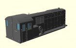
AW 0-6-0 DE 7059 Rear.jpg
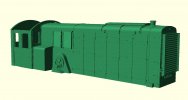
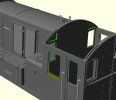
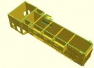
Using the Roche drawing as a starting point and close observation of photographs to try to winkle out any errors in that drawing, I put together this 3D model. An advantage of 3D CAD is that you can manoeuvre the model into the same angle as the reference photo to check the 'look' of something you've changed or added. Needless to say in the absence of proper detailed drawings this is definitely an artists' impression where the finer details are concerned. On the model the roof is a separate part, the light grey parts will be minused out for the final render to leave holes for metal replacements. The glazing pockets are shown in sky blue and translucent, but again will be minused out for the final 3D render. The running plate is there for context and presentation only, and both roof and running plate will be minused for the final 3D render to ensure a good fit and flat bottom respectively.
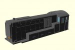
AW 0-6-0 DE 7059.jpg
The Roche drawing? In general the rivets shown are only indicative and not a complete set. The side windows on the cab are too deep and have curved corners at the bottom that should not be there. Not on the drawing is an extra slightly hidden bit between the diesel tank and the battery box (shadows cast in both directions on photos). The bonnet angle is not steep enough and the bonnet doors are slightly different widths to the drawings on both sides. The lid on the bonnet behind the chimney is too short too. The Mercian kit has a few issues as well, but the smaller set of errors are not the same.

There are still a few mysteries. There is no photo evidence of access hatches on both sides for what I think are the diesel tanks. Often seen in operational photos is an S shaped pipe curling up from the pimple on the gear drive cover and going into the cab. There's also often something hanging out from the area of that pimple. I suspect that that pimple might be an outside bearing for the gear drive, but that area is so indistinct in my reference photos that it could be anything. Frustratingly whoever built the loco featured on the box had a pretty good idea how that area looked.

Whilst researching all this, I was reminded that the first MRJ Compendium featured the build of a Sayer Chaplin kit for one of these. I also found out that the October 1974 edition of Model Railways has a drawing and feature on these engines. As I changed to MRC in late 1973, that's had to be ordered to see if that can add to my knowledge. Meanwhile an order has gone in for a 3D print of body and roof, and I await its arrival in the post with what now passes for excitement. This is tinged with trepidation, particularly about whether those glazing pockets can be made to work.
 
Last edited:

Stevers

Western Thunderer
Courtesy of Ebay, that rehoming service for unwanted model railway items, my October 1974, Model Railways (MR) has arrived. The centrespread drawing therein isn't a bad effort, but repeats the error that the lids on the battery box line up with the panels on the front. Not only don't they line up, but there's a lack of symmetry in that front panel too on the real thing. The drawing also sheds absolutely no light on the arrangement of the gear cover, as apart from lacking detail this one is completely the wrong size and shape! The chimney is shown as a handsome thing quite unlike the silly little item that the real thing had. Still a useful extra source though.

Chimney area comparison.jpg
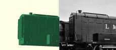
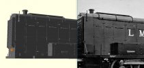
This is an example of positioning the 3D render to compare it with a photo from the same angle. I too am guilty of bigging up the chimney slightly, but if we look at this cruel comparison then my chimney isn't tall enough, and there's too much roof between engine cover and nose panel, or possibly my forward bonnet doors are a fraction too wide. I put this view up not because of those problems, but because the 'lid' is shown as much narrower in the MR drawing than either the kit or Roche has it, and it looks like the truth is somewhere between the two. Chimney and lid will be amended for the 3D print on Monday.

Body - ready to print 2.jpg
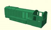
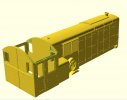
This is a render of the STL file prepared for 3D printing. Although the windows on the side of the cab look wrong on the MR drawing, they did highlight that I needed to lower the bottom of those windows to match the reference photos. The bottom of the side windows should line up with the start of the curve on what MR identifies as the fuel tanks. Note that there is no access hatch on the fuel tank this side on my model, something that the MR drawing may or may not confirm since it doesn't show one the other side either. The drawing also highlighted that front and back windows were probably the same size unlike the Roche drawing, which with the less upright bonnet sides doesn't have room for that, so this too has been changed.

Body - ready to print.jpg


To prepare for the 3D print the roof was minused out to ensure a good fit. This view shows that funny little filler piece between tanks and battery box for which there is no evidence other than shadows. Note the three panels on the front of the battery box are slightly offset to one side. The glazing pockets are 0.3mm, these may or may not leave room for .010" (0.25mm) glazing.

Body - ready to print 3.jpg

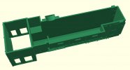
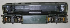
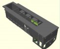
And what's not going on underneath. The scallop is there to clear the connecting rod, and with the lowering of the running plate this becomes more important. Cab walls are 1.2mm and bonnet walls 1.0mm There's a step in at the front to portray the overlapping panelling and its line of rivets. My mechanism is 15mm wide and at 16mm internal width on average there's room for that in there. Whether extra walls and support internally is required remains to be seen. I'd like to do a detailed cab, but I think I'll do that to drop in afterwards. I have some idea of what the consol looked like from the kit, but that's it unfortunately. It doesn't seem unreasonable to borrow some cab fitting ideas from an 08 or one of the larger batch of LMS shunters that were of similar appearance.
 
Last edited:
Stevers

Western Thunderer
Chimney area comparison.jpg

This is the revised comparison. Unable to resist the urge to fiddle, as well as 'fixing' the chimney, I shortened and raised the handrails on the bonnet sides, lowered the top lamp iron, narrowed, raised and lengthened the lid, lengthened the cover, moving verticals and fastenings to match. I adjusted three QCAD drawings and the rest were just a few changes to the the script file that generates the 3D model.

For the record this model (body and roof) required 1500 lines of OpenSCAD scripting and 77 QCAD drawings. The code is structured, making it easier to maintain, and there are modules (sub-routines) within the code to do useful jobs like put out a line of x rivets, of y size and at z spacing, or something similar for an arc of rivets at a specified radius and angular spacing plus size and total number. Much use is made of symmetry along the y axis to mirror those things that are symmetrical (cab and bonnet roof) from one side to the other.
 

simond

Western Thunderer
I’m intrigued by your comment regarding motorisation via the jackshaft.

I can see no reason why it should be a bad idea, particularly if you’ll spring the actual axles. Indeed, it seems to me to offer that benefit particularly well, given it’s the reason the real thing had a jackshaft…
 

Stevers

Western Thunderer
I can see no reason why it should be a bad idea, particularly if you’ll spring the actual axles. Indeed, it seems to me to offer that benefit particularly well, given it’s the reason the real thing had a jackshaft…
I do feel like I chickened out with most of the work required to achieve jackshaft drive and full compensation or suspension done. Springing would have improved the way it moved over lumpy track, but this loco pre-dates the wider adoption of CSB - an approach I thoroughly approve of.

I've only built two engines on the Sharman system (fixed axle), and dislike the way the whole loco moves around that fixed axle. My Wills LBSCR I3 (my very first build), was one of them, and although it holds the road really well, I changed to twin beam compensation for everything after that, apart that is, for this not so little shunter.
 
Last edited:
Stevers

Western Thunderer
P2190502.JPG
Chassis and the now shortened running plate, after some actual messy, smelly modelling.

Overall wheelbase is 60mm (15') when it should be 58mm (14'6"), so proportionally that's slightly worse than the error in the overall length! A complete surprise to me is that the jackshaft is 68.5mm from the front of the chassis which just happens to be where I'd placed the gear cover on my new body. Last night the body was removed from the running plate and valance and rear buffer beam unsoldered. I removed 2.5mm from the rear of the running plate and the same from the front of the valance and soldered it all back together again. The valances are now inset slightly and there's scope to narrow the running plate to a fraction under 35mm (8'9") when it should be 8'7", and I can live with that given the error in the wheelbase. The buffers are fractionally too far apart, but to avoid rebuilding the front I shall leave them as they are. Happily the holes for the cab handrails turned out to be the correct distance apart for my 3D Printed body, so that's shaping up to be another win. My little splasher will need to go as it's too small and too close to the edge, and I've provided for a more suitable one on my 3D printed body.

The chassis is of course now around 2.5mm too long, with the excess to be removed from the cab end. It has a flat top so I'll need to provide a small step at the ends for the flat ends of the shortened and lowered running plate to drop down onto, plus raised areas in the running plate for the chassis to poke up into and mount securing nuts and cab floor. The sanding hoppers are extremely nicely moulded - arguably the best parts in the kit. Sadly, I very robustly mounted the rear ones in a brass tube through the chassis, and that will need to move about 2.5mm forwards to restore their relationship to the cab steps. The sand boxes will then overlap with the brake shoes as they do at the front - so could be worse. This is also true of the guard irons and that scallop in the frame profile, pending a decision on a suspension rebuild, I'll concentrate on shortening the chassis and lowering the running plate.

The current single equilisation beam does pivot on the jackshaft, and that is a very neat arrangement. Changing the suspension to twin beam or CSB with jackshaft drive would be a lot of work for a mere shunter, but is something that I will contemplate if the body 3D prints OK - and that might well be happening as I write this... Twin beams should require less work to retrofit to the existing chassis. For stability (pivot nearer to the centre of the loco), I'd prefer to mount any twin beams on the jackshaft with the motor drive, and that doesn't seem a completely unreasonable approach. CSB though does seem a natural for this not completely to scale beastie, with new frames and hornblocks, but with the existing wheels, motor, gearbox, rods, sanding and brake gear transferred. Still, there's plenty to get on with while I mull that one over!
 
Last edited:

AJC

Western Thunderer
Well, that's a rubber ruler exercise all round, isn't it? I'd be inclined to leave the perfectly decent chassis well alone, mechanically, and save the experimentation for something else. That nice Mr Edge can supply a range of possibilities with like challenges - Mr Bulleid's (uglier still!) 11001 for example.

I know the journey is part of the fun, but it's still nice to finish something (and I know I'm a fine one to talk!).

Adam
 

Stevers

Western Thunderer
Good point Adam, so I promise not to do anything rash - until it's almost finished.

As explanantion perhaps it's time I introduced my old 1990s Mainline Warship chassis to this distinguished group. That would be the one with four sets of Scalextric/MRRC spur gears, four worm drives and chain driven to boot. Fully compensated and I seem to remember once bolster sprung. Sometimes coming up with weird suspension arrangements is an end in itself. If this gets enough likes (well, any likes at all), I'll post that extra special bit of madness here, as I really don't need any encouragement!
 

AJC

Western Thunderer
Quite fast, that Warship, as I remember? Dad's is positively sedate, and the Bachmann version sluggish. None of them could reduce trains in storage sidings to metaphorical matchwood in quite the same way the loco in your avatar did in the hands of an unaware operator...

Adam
 

Stevers

Western Thunderer
Ah yes, 10203, a fully compensated behemoth with six chain driven axles and a 'whitemetal' Q Kits body. It was good for 120mph, and was arranged for Dynadrive with no less than four large flywheels. Unfortunately it was never the same after I drove it off a mantelpiece when demonstrating the inertia feature. :(

2018-01-03_20-49-57_367.jpg
And it was so very nearly 'finished' on a shortened Bachmann Peak chassis when Kernow produced theirs.
A 'laugh' doesn't count as a 'like' by the way!:)
 
Crazy Mainline Warship diversion

Stevers

Western Thunderer
OK, a like and a laugh will do, and note that this is as 'Western' as I've ever got!
P2190499.JPG
Mixed media engineering with a vengeance. The original motor was probably for a mini-drill and cost £2.95, this is a brand new (also cheap) upgrade that made no obvious difference. I believe the flywheels are the Dynadrive ones in a cradle suspended on rubber pads. In the middle is a reduction Delrin chain drive down to the drive shaft for the bogies - the frame also mounted on rubber pads. A silicon(?) rubber tube works as well as anything to connect everything up.

P2190497.JPG
This thing is so old that it was made in Hong Kong. Even with steel tyres, you can't have enough weight. Each wheel set has it's own scratch built gearbox, each with its own worm and the MRRC spur gears are used to gear up the final drive. Those gearboxes swivel on the worm axle to provide compensation. There's very little left of the Mainline bogies and then only round the edges. All done without glasses - and that does seem remarkable now. 10203 had the advantage of a mechanism needing only two 14:1 worms - much more efficient. These worms are likely to be 27:1 and Romfords.

P2190504.JPG
The cardan shaft drive is to the inside end of the bogies, limiting it to curves not less than 3' 6" radius. Due to manufacturing intolerance, the cardan shafts are not exactly the same length and therefore not quite interchangeable. The UJ balls for the carden shaft end were from North West Short Lines then about the only people that supplied them. The pins have been replaced in steel and the sockets are home made after the originals split. The problem with four sets of worm gear is drag, and whilst it has a 90mph top speed, it does slow down a bit with twelve on, though I like to think that's more of a problem with the aged YMRG Gaugemaster controllers no longer having enough grunt. At speed it sounds like there's a lot going on in there - I'm told not unlike the real thing - and without a chip in sight!

If I ever felt the need to do this again I'd replicate the later 10203 design with 14:1 worm to the inside axle and delrin chain drive within the bogie though the smaller Warship wheels may not be quite large enough for that approach. Happily with the improvements in ready-to-run mechanisms, this sort of nonsense is no longer necessary - although I seem to remember that it was fun to do at the time!
 

Stevers

Western Thunderer
Well this is (a) very exciting and (b) seems to be happening much more quickly than I expected!

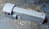
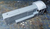
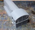
20240219_175953.jpg20240219_180005.jpg20240219_180017.jpg
Apparently the roof supports need revisiting, but this is already arguably better than the slightly wonky etched body. Now I'm desperate to know how those glazing pockets came out!
 

Stevers

Western Thunderer
IMG_20240222_151749882_HDR.jpg
Before I can think about fitting the body I had to reduce the overscale running plate height, so I started by opening up the centre of the running plate with a fretsaw leaving a short ledge at each end for the flat bits behind the cab and in front of the bonnet. I then cut a notch at each end of the chassis for these ledges to sit into. The plan was to shim this area to the correct ride height. Next stage was to fit a couple of saddles to span the gap over the chassis fixing holes with captive nuts. The saddles were spaced up .022" thinking this should be enough for a little adjustment, and they were tack soldered in place, and then soldered up properly - so far so good. This was when things got interesting since the running plate was now lodging on the lower part of the gear case and the sanding fillers, and was catching on the top mounted pick ups causing a dead short. The running plate was opened up slightly to clear the gear casing and sand fillers, and the ends of the pickups shortened to clear the running plate.

As can be seen at the correct ride height, the wheel flanges are almost visible above the running plate, and the treads are therefore very close to the underside of the running plate. With shims only at the end to set the ride height, tightening the fixing screws caused the running plate to deform losing any clearance that there was. The solution to this was to introduce .010" shims under the saddles, and in this condition it was back to its normal robust self. You do have to love what a big motor and two flywheels can do! Cue slightly wobbly phone vid:

Next problem is that the gap in the running plate is 19mm whilst the new 4mm scale bonnet is 18mm* wide externally. There's little scope to make the gap any narrower as at the very least it is likely to foul the centre wheels which need sideplay. I think a thin .050" N/S shim strip along the top of the gap for those parts of the running plate where a gap against the bonnet would be visible. Even when it was riding higher I had put insulating tape under the body to stop shorts, and will either do that or add a strip of epoxied paper after the body is fitted. It looks like it is still chipped for DCC so precautions against shorting are even more important.

Whilst I await the arrival of the 3D printed body I will restore steps and sanding gear, and get on and replace those guard irons.

[Edit] *The width of the bonnet at the nose is 18mm as it has a vertical cutoff at the bottom. The width of the rest of the bonnet is 19mm.
 
Last edited:
Stevers

Western Thunderer
P1010498.JPG
The 3D printed body and roof was collected from the model railway exhibition at Compton Dundon, and to my mind the whole is a masterclass in 3D printing exceeding all expectations. Unfortunately it was immediately apparent that the shortened running plate was now too short, so just over half of what had been removed has been replaced. Conveniently I remembered the spare pair of valances that came with the extra chassis etches and was able to use those. Given the lack of room under the cab for steps, sanding gear and vacuum(?) cylinders this can only be regarded as a very happy accident! The body and running plate are only balanced on the chassis in the photo and the body is a fraction forward of where it will end up. The bit of the running plate round the gear cover has been patched to fit the 3D printed splasher, and the fit of the body is now good. The battery box was slightly outboard of the cab side and a hair drier was all that was required to warm the body up enough to move it inboard again.

Blocking the body from dropping down onto the running plate were the veroboards that the pickups and electrics were mounted on, these disintegrated on being shortened and all of them are being replaced with slightly narrower equivalents made from copper clad glassfibre board. Since the flywheels are 16mm diameter and this is the internal width of the body half way up, the motor needs to be as low as possible for clearance, and another way of restraining the rear of the motor will be needed.

The glazing pockets are visible, but I haven't attempted to drop any glazing into them yet.
 

Stevers

Western Thunderer
P3090515.JPG
Quite a bit of messy modelling (with rubber ruler) has resulted in a running chassis with everything more or less where it should be. As a result of all that messing about, the body is starting to look a little grubby. The fit of body to running plate is a bit gappy, and the compromised rivet detail along the running plate suggests that the very bottom of the body has not been fully printed or has been damaged during support removal.

P3090499.JPG
The fragile Veroboard pickup boards have both been changed to use copper clad fibreglass. Slightly longer pickups were fitted in the same style to sink the ends a little further below the running plate. The gearbox is a Road Runner Plus and has an extra swiveling drive extender that means the motor needs to be held firmly somewhere near the middle. To slightly lower the motor and replace the shanky looking wires that previously restrained the motor, a copper clad fibre glass cross member was epoxied across the frames with a nickel silver strip soldered to it. This strap wraps over the motor and is secured with a 1/32" brass strip bent in two. To secure the overlap it has been tapped 10BA to take a clamp screw. A rectangle of styrene card that exactly fits the cab locates the body in the correct place on the running plate, and is temporarily held down with some lead,brass and a nut.

P3090509.JPG
Although the front sanding hoppers in their original position are a little too far outboard, it would be difficult to move them inboard as the brake shoes are behind them. They looked credible where they were, so I remounted the rear sand hoppers the same way because they too are outboard of a set of brake shoes. Once that was done I could epoxy the sand pipes back in. The wheel base should be 58mm, the Mercian wheelbase is 60mm and the wheelbase of the not dissimilar Derby built shunters (as available from Judith Edge Kits) is 61mm (in 4mm scale).

P3090514.JPG
The lack of a flat bottom to the body is very obvious here. Although the buffer height is fractionally higher than my vans it's a bit lower than my Mainline Warship, Westward T9 watercart tender and other stock, which is probably why it was the height it was. The chassis runs well on its own, but there is a mysterious dead short if I fully tighten the front chassis to running plate screw. Raising the running plate with thin card shims might well resolve the short whilst not raising the buffer height significantly.

front-rear glazing pockets.jpg
The glazing pockets for the cab sides were correctly formed, but would only take a thin bubble packaging film rather than the intended 0.25mm Plastiglaze. The problem here is that holes 3D print too small and rods too large. The glazing pockets were nominally 0.3mm and I have increased that to 0.45mm. It is unclear to me if this is due to pixelation, light leaks, a resin film effect or some combination of these. In my experience it varies between suppliers, with the latest batch of 'Verwood' cranes from the same supplier faring well in this respect. The glazing pockets over the front and rear windows were not fully formed as they had retained resin that had subsequently set, so I've opened them up so that there are just two strips across the pocket which should allow the resin to drain.

Braces and Flywheel Scallop.jpg
To address problems with the distortion of the base of the body, I have added braces across the body (waisted at each end) that can be snipped out. Those large flywheels rub lightly but noisily against the body sides so to address this I've added scallops (shown in green) inside the body to give clearance to them. It will also be necessary to slightly extend the body downwards so that there is enough material to flatten the bottom on a sheet of silicon carbide paper glued to a board to improve the fit and to make sure the bottom rows of rivets print OK.

It was always unlikely that I would get the 3D print right first time, and although this was designed to replace the overscale brass etched body resolving that problem, it's really just as much to do with working through what might or might not work for the 1860s LSWR coaches that I need for the block set that derailed at Downton. The glazing pockets behind the vents will certainly have to be revisited based on what's happened here.
 

Stevers

Western Thunderer
Revised Battery Box.jpg
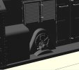
The original slope on the battery box lids was taken from the Roche Drawing, but compared with photos this was a little on the steep side, so I have reduced the slope slightly. This was quite easy as I'd built the lids 'level' and added the necessary slope at a late stage. I also had no photographic evidence for my filler piece between battery box and the diesel tanks; there's only evidence for some sort of gap, and it would be much easier to put a filler piece if required than to remove one that was printed in, so a gap it is.


Speedo Drive.jpg
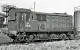
Looking at the area of the pimple on the gear case on the three prototype photos that I have that show this area at all, it dawned on me that the 'pipe' and small box below the pimple looked very much like a speedometer drive, in the perfect place for one to be. The pipe/cable exits from the end of the small box and snakes up to the cab in an 'S' shape avoiding sharp corners, as might be expected, and would put the 'speedo' just above the offside front window. The problem with this is that an alleged top speed of 20mph (Wiki), makes any sort of speedometer an ornament, so more likely this was just an odometer. Maintenance perhaps being linked to both miles and hours run.

Body v2 - ready to print 2.jpg
A render of the body ready for the second print attempt, showing the holes in cab front and gear box ready to receive a 0.45mm wire to represent an odometer cable. As for the buffer height, I cut a strip of styrene at 13.8mm and this confirmed that with 0.2mm ABS shims under the running plate the buffers are at the correct height, matching both the Warship and the Watercart tender that were to hand. The troublesome trucks that tried so hard to mislead me have a buffer height set at around 13mm, and that apparently is within the acceptable range of buffer heights in the UK (in 4mm scale) which can be as low as 12.5mm - according to one source on S4F. The shims resolved the dead short, and put the running plate pretty much back to where it started, and there's surely some sort of a lesson to be learned in that! :rolleyes:

Body v2 - ready to print.jpg
The motor mount can be tweaked so that the flywheels rub on either one or other side of the body - or it turns out, if bang in the middle, not rub at all! There isn't a lot of room in there for the 16mm flywheels, so I'll still go with the extra clearance from the scallops I've added. 0.2mm has been added to the bottom of cab, bonnet, tanks splasher etc. This with a view to retaining the rivet detail along the running plate, and giving me scope to true up the base of the body before gluing it to the running plate. I've also brought the bonnet down to running plate level behind the battery box and tanks. The evidence from the first print suggests that the model when removed from the resin tank is pretty flexible until fully cured, and the removable braces and boxing are intended to address this lack of stiffness.

There is an etched control panel in the kit, so I think the next job is knock something up that looks a lot like that, but fits in the smaller cab, and to refit the cab steps and vac/air tanks under the rear buffers.

[Edit] Have just found a photo of what claims to be a Class 08 speedo (up to 20mph), but red lined at 'only' 15mph!
 
Last edited:
Tim Hale

Western Thunderer
Compton Dundon was mentioned, who organised the event? I did not notice it in any of the usual places and a previous visit
was inspirational.

Thank you
Tim
 
Top