Mike G's Workspace.

Mike Garwood

Western Thunderer
All the coach corridor connectors have been completed. Hopefully I’ve got the width right for the coach couplings so that the ends of the coach spring against each other. Time will tell.
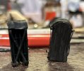
Coach bellows completed.jpg

Next up is a GWR Grange 6810 – Blakemere Grange. I have a photo of her blasting thru HHL with a freight train and a photo of her with coaches having just left Pontypool Road. I’m not the owner of these photos and I don’t know who the photographer is, so it would be bad form to post them into this.

Another kit has made it from the ‘shelf of shame’. I have a Malcolm Mitchell Collet 4000 gallon tender kit (compensated), aligned with a Hornby body, Comet chassis (which will be sprung), Gibson wheels and the Brassmasters slide bar and crossheads up-grade kit. That will make up 6810.
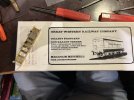
GWR Collet 4000 Gallon tender1.jpg

I made a start on the chassis this pm and it’s virtually self-jigging, but I did put it on the jig (red box) to add a belt and braces approach. The only problem I encountered was the bearings that go into the compensated front and middle wheel sets, the etch had to slightly teased out with a light filing to get the bearings to fit nicely and move up and down without sticking. Really looking forward to building the rest of this. The only fly in the ointment is forming the flare on the tender sides.

If anyone has any good ideas, I’m all ears. The last time I did this was 25 odd years ago on a 3500 g tender, same designer. It isn’t a happy memory and I really struggled to get a uniform curve. So if you’d like to share your technique it would be hugely appreciated.

I’m going to be in loco building mode for a good while. 3 panniers – including a 16xx – and 2, 43xx, one has the Dapol body, which is excellent, the other will be another Malcom Mitchell kit. EXCITING! Once these are built that will be all the operational engines completed for HHL. Unfortunately or not, I have found more coaches that have appeared in other photos and these will be paired with the engines in progress – as per the photos. This means that every train will be historically correct, just might not have appeared in the same time continuum.

So this year I shall be shifting 6 kits, not that this will dent or improve my lack of shelf space for kits. It’s only a couple of months since I put 2, 8” shelves up in my study and my ever loving wife filled them with her crap. Correction, I did manage to get my regular reference books on. All two feet of them…awesome!

Stay safe


Mike
 

45609

Active Member
The only fly in the ointment is forming the flare on the tender sides.

If anyone has any good ideas, I’m all ears. The last time I did this was 25 odd years ago on a 3500 g tender, same designer. It isn’t a happy memory and I really struggled to get a uniform curve. So if you’d like to share your technique it would be hugely appreciated
We'll talk about it next Friday mate.
 
Last edited:

Mike Garwood

Western Thunderer
Back to the 51xx for a moment...in post 653, Yorkshire Dave suggested that weight alone should keep the radial truck on the road. After a lot of consideration (about 2 minutes) and the fact that the springing solution I devised was a non starter, I put as much lead on top of and around the truck...it works and if it works, don't fix it! So, thank you Dave. Just goes to show that sometimes the simple solution is the right one - well it was on this occasion.

Moving on...

I've made a start to 6810 Blakemere Grange. I used the Brassmasters 43xx etch for the slide bars and I moved the centres out 1mm either side to allow some clearance for the crossheads and the front driver (documented on post 658). Unfortunately, there are no drain cocks in whitemetal or brass castings to be had - I couldn't find anything on my web searches (not available from Brassmasters as they do not sell individual castings unless they are already in their 'Accessories' list.)
And I didn't have time to draw some up and get them etched...now on my to do list as there are still more engines that will require a similar type. I settled on copper wire with brass tops.

Grange drain cocks.jpg

The cylinders and connecting rods are now complete and drying on the radiator. Then I turned my attention to the chassis and the coupling rods. I must be slowing down, as it's taken me all day to do this. I have had to go to the dreaded dentist for more work, or rather a continuation of wisdom teeth problem. Que laughter....

Dentist torture chamber.jpg

Anyway, rods are complete, I'd forgotten just how much effort goes into doing these. The bearings had to have a little bit removed for the side slides in order to get them to move freely in the chassis openings and just for good measure I removed the etched lines within the those as well.

Grange coupling rods.jpg

Grand parenting duties tomorrow with Harry (more Paw Patrol), so dismantling the Hornby model will have to wait.

From Saturday morning onwards the dinning room switches identity to a paint studio as SWMBO is off on her hols! :) . There's 4 coaches to be done and quite a bit of weathering.

I'm eyeing up the offers on Stella as I type this...

Stay safe

Mike
 

Dangerous Davies

Western Thunderer
Are you having wisdom teeth fitted Mike?
The last time I saw shades like yours was on an operator burning outer laps off a coil on M2 entry!
Seriously, the Grange project looks interesting.
Cheers
Dave
 
Last edited:

Mike Garwood

Western Thunderer
Saturday at 10:28 BST, SWMBO left the premises for her hols. I had Grand parenting duties to perform for a couple of hours before I could get stuck into making a mess of the dining room.
By half past four the room looked like this:

The carnage begins.jpg

Most of the candidates had gone into primer...whilst this was drying I got on with the Grange.

Having got the bearings into the chassis sides, it was time to decide how to secure the body to the chassis. This is where you need to be careful where you place the chassis spacers...and don't forget that your chosen gearbox and motor have to fit as well. I've gone for a High Level; Road runner plus and the 1230 coreless motor, which will drive from the centre axle. 45:1. This should mean that theres a good turn of speed as well as the ability to move slower with a set of wagons on. I have a photos of 6810 starting out of Pontypool road with 4 on the back and another of her steaming thru Hengoed HL with a goods train.

Out with the Red box, fire up the soldering iron and off we go. The chassis being complete and the cylinders completed as well it was time to marry body and chassis together.

GWR 6810 body shaping.jpg

As you can see there is some destruction to be completed before the chassis will fit. First is a block of plastic under the cab to be removed and then several body supports under the footplate to be shortened. The rear axle openings for wheels also has to be widened. Fortunately, there is enough plastic to be removed without causing any damage to the body.
I have to say the Hornby model is quite superb (oddly the tender is not of the same quality - hence the build of the Mitchell tender), there is nothing to be added to the body and the cab interior isn't that bad either. The existing cabside numbers came off with a fibre pencil.

GWR 6810 fames and cylinders complete.jpg

Chassis together, wheels in the centre of the body wheel arches, cylinders snuggly touching the footplate. Fair play Comet!
This as far as I've got with the engine, I'm debating whether to try and spring or compensate the bogie. This will go into primer tomorrow and then a blast of cellulose BR green.

Back to the paint studio. Out with the cellulose gloss black to do the coach under frames and cosmetic bogies sides and couplings. I used my very trusty Asturo air gun. This now has a new 0.5mm needle in. The difference between the original 0.3 and the 0.5 needle is quite noticeable. I certainly get a bigger flow of paint with the 0.5 and I have to have a gentle touch on the trigger to avoid a flood.
The sides and roofs have been completed and are drying/ hardening. Next job is to paint the interiors.

sides and roofs complete.jpg

Tomorrow will see the ends masked off and the ends receive some Vallejo matt black. Once that's dried I can start with the lining.
It's all go and fabulous fun and seeing these come to life is very satisfying.

Stay safe.

Mike
 

Attachments

  • Primer done cosmetic sides complete chassis complete.jpg
    Primer done cosmetic sides complete chassis complete.jpg
    160.5 KB · Views: 7

timbowales

Western Thunderer
Saturday at 10:28 BST, SWMBO left the premises for her hols. I had Grand parenting duties to perform for a couple of hours before I could get stuck into making a mess of the dining room.
By half past four the room looked like this:

View attachment 236176

Most of the candidates had gone into primer...whilst this was drying I got on with the Grange.

Having got the bearings into the chassis sides, it was time to decide how to secure the body to the chassis. This is where you need to be careful where you place the chassis spacers...and don't forget that your chosen gearbox and motor have to fit as well. I've gone for a High Level; Road runner plus and the 1230 coreless motor, which will drive from the centre axle. 45:1. This should mean that theres a good turn of speed as well as the ability to move slower with a set of wagons on. I have a photos of 6810 starting out of Pontypool road with 4 on the back and another of her steaming thru Hengoed HL with a goods train.

Out with the Red box, fire up the soldering iron and off we go. The chassis being complete and the cylinders completed as well it was time to marry body and chassis together.

View attachment 236172

As you can see there is some destruction to be completed before the chassis will fit. First is a block of plastic under the cab to be removed and then several body supports under the footplate to be shortened. The rear axle openings for wheels also has to be widened. Fortunately, there is enough plastic to be removed without causing any damage to the body.
I have to say the Hornby model is quite superb (oddly the tender is not of the same quality - hence the build of the Mitchell tender), there is nothing to be added to the body and the cab interior isn't that bad either. The existing cabside numbers came off with a fibre pencil.

View attachment 236173

Chassis together, wheels in the centre of the body wheel arches, cylinders snuggly touching the footplate. Fair play Comet!
This as far as I've got with the engine, I'm debating whether to try and spring or compensate the bogie. This will go into primer tomorrow and then a blast of cellulose BR green.

Back to the paint studio. Out with the cellulose gloss black to do the coach under frames and cosmetic bogies sides and couplings. I used my very trusty Asturo air gun. This now has a new 0.5mm needle in. The difference between the original 0.3 and the 0.5 needle is quite noticeable. I certainly get a bigger flow of paint with the 0.5 and I have to have a gentle touch on the trigger to avoid a flood.
The sides and roofs have been completed and are drying/ hardening. Next job is to paint the interiors.

View attachment 236175

Tomorrow will see the ends masked off and the ends receive some Vallejo matt black. Once that's dried I can start with the lining.
It's all go and fabulous fun and seeing these come to life is very satisfying.

Stay safe.

Mike
Does Mrs G ever get to see these photos?
 

Mike Garwood

Western Thunderer
Another busy day, masking off the ends of the coaches and painting the grange into Bronze green. There were other house hold chores to be completed first and then Grand parenting duties with my wonderful Grandson Harry.

The Grange has come out really well.

GWR 6810 in paint.jpg

And for a change the masking of small bits has worked.

Coaches painting completed.JPG

Not the best of pictures...
Take it from me that there's no leaking on the sides, there will be some touching up to do. I've also completed the interiors as well. Tomorrow is a day off, but I'll probably start the lining and looking coach numbers in the evening. With the demise of Model master (the website seems to have disappeared), I'm not sure who to go to to get the coach numbers that match these coaches. Any suggestions gratefully received.

A good day all round.

Stay safe

Mike
 

ullypug

Western Thunderer
Another busy day, masking off the ends of the coaches and painting the grange into Bronze green. There were other house hold chores to be completed first and then Grand parenting duties with my wonderful Grandson Harry.

The Grange has come out really well.

View attachment 236293

And for a change the masking of small bits has worked.

View attachment 236294

Not the best of pictures...
Take it from me that there's no leaking on the sides, there will be some touching up to do. I've also completed the interiors as well. Tomorrow is a day off, but I'll probably start the lining and looking coach numbers in the evening. With the demise of Model master (the website seems to have disappeared), I'm not sure who to go to to get the coach numbers that match these coaches. Any suggestions gratefully received.

A good day all round.

Stay safe

Mike
Mike
Railtec do a bespoke coach numbering service
 

Captain Kernow

Western Thunderer
Mike, I'd be interested in your experience with the springing on the Grange chassis and how well the rods correspond with the axle holes in the sprung bearings. Hopefully there's no chance that they would move in any direction other than up and down?
 

Mike Garwood

Western Thunderer
Captain my Captain...Strange you should mention that...

In the chassis kit you get 2 options of coupling rods, the older/ original rods that were fitted and also the updated version. Without checking my sources I opted for the newer version. There are 2 ways of building these rods. Jointed by rivet ( my preferred option) and the original split version.
I use the chassis construction aid (Avondale) that was last sold by Eileens and was the brain child of Robin Whittle for my chassis building.

Having put the bearings into the chassis - this wasn't as straight forward as you may think - I filed off the etch cusp, being really careful not to take anymore than was needed. Even then some of the bearings would not fit. I opened out the sides of the bearings, as it appeared to me that this was where the problem was. Some still didn't move as nicely as I would expect or want. No other option but to file a little more off both sides (what would have been the sub horn block) and after every slide of the file check the fit of the bearing. After much trial and error I got them in. Each one now moves up and down with no side to side rocking.

Moving to the rods...and this was a f==k up of my own making, I drilled the rivet hole with a 1mm drill - should have been a 0.7mm drill. Yes this made a huge difference! But the interesting part was that when I lined these rods up on the jig, I could not get the rear axle to mount the jig (sounds like something out of a Compton McKenzie novel). Now this may have been my fault, having introduced one element of cock handedness, I may have also introduced a second as well.

I've built A few of these types of chassis before and never experienced any of the problems outlined above before. Both of these were 2 56xx's and if you've looked at my Utube channel, you'll know that they are incredibly smooth.
So before I place another order for more coupling rods I re-examined my source material, a number of good photos are available of 6810. It might have been my imagination but it looked to me as though the couplings rods had not been changed (you can tell by the amount of metal that comes from the head of the coupling rod into the body, the newer version has a lot more there than the older type).
So I scrapped this set of coupling rods and built the originals. All good, fitted without problem. I have yet to open them out to 1.6mm. The building rods on the jig measure 1mm, so that was what I used to drill the holes. I shall probably ream out these openings rather than chance a cock up on the drill. And I'm going to have to check the collet on my drill to see if the drill is centring properly or if it's being pulled to one side.

My own view as to weighting of the body...I think the springs are a touch stiff and to get them to act, you need more weight than if you were to use CSB's. This is my own view and born out of my experiences to date.
Knowing that I'm going to add more weight to the body this has affected my choice of gearbox and motor. I do like a chunky motor :) .

Hope that's helpful.

Mike
 

Captain Kernow

Western Thunderer
Captain my Captain...Strange you should mention that...

In the chassis kit you get 2 options of coupling rods, the older/ original rods that were fitted and also the updated version. Without checking my sources I opted for the newer version. There are 2 ways of building these rods. Jointed by rivet ( my preferred option) and the original split version.
I use the chassis construction aid (Avondale) that was last sold by Eileens and was the brain child of Robin Whittle for my chassis building.

Having put the bearings into the chassis - this wasn't as straight forward as you may think - I filed off the etch cusp, being really careful not to take anymore than was needed. Even then some of the bearings would not fit. I opened out the sides of the bearings, as it appeared to me that this was where the problem was. Some still didn't move as nicely as I would expect or want. No other option but to file a little more off both sides (what would have been the sub horn block) and after every slide of the file check the fit of the bearing. After much trial and error I got them in. Each one now moves up and down with no side to side rocking.

Moving to the rods...and this was a f==k up of my own making, I drilled the rivet hole with a 1mm drill - should have been a 0.7mm drill. Yes this made a huge difference! But the interesting part was that when I lined these rods up on the jig, I could not get the rear axle to mount the jig (sounds like something out of a Compton McKenzie novel). Now this may have been my fault, having introduced one element of cock handedness, I may have also introduced a second as well.

I've built A few of these types of chassis before and never experienced any of the problems outlined above before. Both of these were 2 56xx's and if you've looked at my Utube channel, you'll know that they are incredibly smooth.
So before I place another order for more coupling rods I re-examined my source material, a number of good photos are available of 6810. It might have been my imagination but it looked to me as though the couplings rods had not been changed (you can tell by the amount of metal that comes from the head of the coupling rod into the body, the newer version has a lot more there than the older type).
So I scrapped this set of coupling rods and built the originals. All good, fitted without problem. I have yet to open them out to 1.6mm. The building rods on the jig measure 1mm, so that was what I used to drill the holes. I shall probably ream out these openings rather than chance a cock up on the drill. And I'm going to have to check the collet on my drill to see if the drill is centring properly or if it's being pulled to one side.

My own view as to weighting of the body...I think the springs are a touch stiff and to get them to act, you need more weight than if you were to use CSB's. This is my own view and born out of my experiences to date.
Knowing that I'm going to add more weight to the body this has affected my choice of gearbox and motor. I do like a chunky motor :) .

Hope that's helpful.

Mike
Thanks Mike, that is indeed helpful. I am debating whether to use the Comet springing system for the next loco I am likely to build (an Austerity 0-6-0ST) and your comments about fettling the bearings and hornblock openings confirm my suspicions about that. It's also interesting to read your comments about weighting and the effect on the springs. I may yet opt for my preferred method of simple compensation....

But I'll check out your Youtube channel and watch those 56XXs in action! The Grange is coming along nicely as well!
 

Bulldog3444

Active Member
Thanks Mike, that is indeed helpful. I am debating whether to use the Comet springing system for the next loco I am likely to build (an Austerity 0-6-0ST) and your comments about fettling the bearings and hornblock openings confirm my suspicions about that. It's also interesting to read your comments about weighting and the effect on the springs. I may yet opt for my preferred method of simple compensation....

But I'll check out your Youtube channel and watch those 56XXs in action! The Grange is coming along nicely as well!
Tim,

I don’t think that the question is so much about compensation or springing, but rather whether the axle spacing is going to be determined by the frames or the rods.

if you are going to use the frames as etched, and the hornblocks as provided with the frames, to determine the spacing then in order to get smooth running you need to make the coupling rods match those spacings (including taking account of things like the hornblocks being drilled off centre.) I don’t find it easy to adjust the rods to match the frames.

The alternative is to make the rods first, and then use them to set the hornblocks within the frames. I find this easier, using either High Level or MJT hornblocks. They can be used either will compensation or springing.

Whichever option one goes for, getting the axle spacing matching the coupling rods is worth really taking time over, as it’s fundamental to good running. I’ve spent too many hours trying to sort out chassis where this hadn’t been achieved.

And nice to see the progress with the Grange, Mike - I’ll look forward to the video of it running in due course.

Ian
 

Captain Kernow

Western Thunderer
Whichever option one goes for, getting the axle spacing matching the coupling rods is worth really taking time over, as it’s fundamental to good running. I’ve spent too many hours trying to sort out chassis where this hadn’t been achieved.
Absolutely Ian and that has been a fundamental tenet to my own chassis building ever since I first started building etched chassis.

My query is more about the design of the Comet springing system and their chassis. As I understand it, using the Comet system, there are no hornblocks as such, rather the square bearings slide in the cut-outs in the Comet frame, with a small etched 'spigot' at the top to trap the spring. As such, there is no apparent way of varying the distance between the bearings. It's a bit like building a Comet chassis entirely rigid. You rely on the Comet measurements for the rods matching that for the frames exactly. This is not so much a problem if the rods are etched in direct correlation to the axle holes in the frames - a friend who used to draw his own etching masters out on card taught me that, but if the rods are elsewhere on the fret (eg. at right angles to the frames), then one relies on the designer to get the relationship between the two spot on in the first place.
 

timbowales

Western Thunderer
Absolutely Ian and that has been a fundamental tenet to my own chassis building ever since I first started building etched chassis.

My query is more about the design of the Comet springing system and their chassis. As I understand it, using the Comet system, there are no hornblocks as such, rather the square bearings slide in the cut-outs in the Comet frame, with a small etched 'spigot' at the top to trap the spring. As such, there is no apparent way of varying the distance between the bearings. It's a bit like building a Comet chassis entirely rigid. You rely on the Comet measurements for the rods matching that for the frames exactly. This is not so much a problem if the rods are etched in direct correlation to the axle holes in the frames - a friend who used to draw his own etching masters out on card taught me that, but if the rods are elsewhere on the fret (eg. at right angles to the frames), then one relies on the designer to get the relationship between the two spot on in the first place.
Unfortunately Comet seem to use separate etches for frames and motion as they are supplied separately and using different materials :(
 
Top