You are using an out of date browser. It may not display this or other websites correctly.
You should upgrade or use an alternative browser.
You should upgrade or use an alternative browser.
2mm Modbury
- Thread starter Ian Smith
- Start date
Joe's Garage
Western Thunderer
Ian you are so modest.....
"were hand painted with a fine brush."
The Duke is exquisite
ATB
Julian
"were hand painted with a fine brush."
The Duke is exquisite
ATB
Julian
Tim Watson
Western Thunderer
And now for the Dean single…
You know you want to.
Tim
You know you want to.
Tim
Ian Smith
Western Thunderer
Tim, my next loco project is going off piste - I have a Midland 1400 class 2-4-0 to build. A favourite of mine since having built a non running Ratio one in OO as a teenager. Don’t tell anyone but I think that Johnson’s engines were nearly as attractive as William Dean’sAnd now for the Dean single…
You know you want to.
Tim
Ian
Joe's Garage
Western Thunderer
I will certainly look forward to that one if the Duke is anything to go by.....more "fine" brushes I guess Ian??!!
Cheers
Julian
Cheers
Julian
Last edited:
simond
Western Thunderer
Nearly…Don’t tell anyone but I think that Johnson’s engines were nearly as attractive as William Dean’s

(GWR 2602 Class - Wikipedia)
I think I’d want extra pay if i had to drive that…
Joe's Garage
Western Thunderer
One of WD's off day...?
Grahame Hedges
Western Thunderer
Eeee gads. That's ugly.
Ian Smith
Western Thunderer
Since its been a few years since I last made a proper video of Modbury, over the festive period I took the opportunity to film (and edit) an up to date sequence of train movements. The content was all filmed on my now ancient iPhone 7 on a tripod while also managing the movement of the trains and whilst also trying to keep the right bits in focus!!
Hopefully some of you will enjoy ...
Thanks for looking.
Ian
Hopefully some of you will enjoy ...
Thanks for looking.
Ian
Grahame Hedges
Western Thunderer
Although I'm not a great steam loco enthusiast, I am interested and impressed by the engineering and construction of these models, and in particular N/2mm scale modelling. The locos, and trains, run sweetly, steadily and smoothly, integrating in to the period scenery seamlessly and enhancing the overall scene. The railcar a particular joy. Beautiful and proficient modelling and inspiration.
Ian Smith
Western Thunderer
Some time ago I started a little side project - a bank of Scalefour Society Lever Frames - this was to be something that I could take along to our fortnightly Midland Area Group meetings that would be pretty self contained.
With the main construction completed at our meetings (the assembly of the frames and levers over the last couple of months or so), the last couple of weeks at home has progressed onto the painting and final assembly stage.
The 3 frames were joined together (I originally built 4 but decided that I would remove all but one of the "spare" levers and renumber my present control panel switches to suit the 15 levers in the 3 frames). Once cleaned they were sprayed in Upol 8 self-etch primer, then received a coat of satin black from a rattle can.
The 14 levers that I needed had been soldered up from the 3 layers of etch for each, cleaned up and the handle mounting spigot at the top was filed to a round section about 1.4mm diameter then had a 10BA thread put on. At the time that I purchased the lever frame kits (from an exhibition) I was unable to purchase the turned handles (Jeremy had run out), so instead I elected to turn my own which before shaping had been drilled and tapped 10BA to suit the thread on the mounting spigot on the lever itself.
Over the last few days, the top 45mm of each lever received a coat of Upol 8, then were brush painted with Ammo acrylic paints. The lever numbers which hadn't been painted (apart from primer) were given a coat of black ink, then a fine file run across the face to pick out the etched numerals and surround.
This is the first time that I have used the Ammo paints, and was pleasantly surprised by their covering power.

One of the Facing Point Lock levers ready to be installed in the frame.

The completed lever frame with all of the levers and their respective microswitches installed (the two FPL levers don't need microswitches).

Completed lever frame from the rear. The levers sit in "shoes" which slide forward and backward driving the 0.9mm rods that can be seen at the back of the frame. Eventually, I intend to add a locking frame to the rear of the leverframe and these rods will be connected to the tappets.
Thanks for looking
Ian
With the main construction completed at our meetings (the assembly of the frames and levers over the last couple of months or so), the last couple of weeks at home has progressed onto the painting and final assembly stage.
The 3 frames were joined together (I originally built 4 but decided that I would remove all but one of the "spare" levers and renumber my present control panel switches to suit the 15 levers in the 3 frames). Once cleaned they were sprayed in Upol 8 self-etch primer, then received a coat of satin black from a rattle can.
The 14 levers that I needed had been soldered up from the 3 layers of etch for each, cleaned up and the handle mounting spigot at the top was filed to a round section about 1.4mm diameter then had a 10BA thread put on. At the time that I purchased the lever frame kits (from an exhibition) I was unable to purchase the turned handles (Jeremy had run out), so instead I elected to turn my own which before shaping had been drilled and tapped 10BA to suit the thread on the mounting spigot on the lever itself.
Over the last few days, the top 45mm of each lever received a coat of Upol 8, then were brush painted with Ammo acrylic paints. The lever numbers which hadn't been painted (apart from primer) were given a coat of black ink, then a fine file run across the face to pick out the etched numerals and surround.
This is the first time that I have used the Ammo paints, and was pleasantly surprised by their covering power.
One of the Facing Point Lock levers ready to be installed in the frame.
The completed lever frame with all of the levers and their respective microswitches installed (the two FPL levers don't need microswitches).
Completed lever frame from the rear. The levers sit in "shoes" which slide forward and backward driving the 0.9mm rods that can be seen at the back of the frame. Eventually, I intend to add a locking frame to the rear of the leverframe and these rods will be connected to the tappets.
Thanks for looking
Ian
Ian Smith
Western Thunderer
Over the last couple of weeks since the Bournemouth Exhibition, I've been installing the new lever frame into the existing control panel. This has involved making a new top surface for the control panel (onto which I could bolt the new frame), which also covered the various holes in the existing one where the switches used to protrude. This new top has also had a sloping front built up onto it to a) hide the front of the frame/micro switches and the wires there, and b) to provide a little more space to site the signalling diagram and the lever leads.

This view shows the old control panel (photo taken at the Loughborough exhibition a few years ago) with the old set of switches.

The revised control panel with the new lever frame. As can probably be seen, the old version had space for some 18 switches (4 of which weren't used but allowed the switches to be spaced and grouped - switches 17 & 18 for example controlled the points in the yard that would have had local hand levers). In replacing with a lever frame, I have taken the opportunity to remove the redundant spaces, this has meant that the switches north of number 7 have all been reassigned, and has also provided an opportunity to swap the numbering of the Down signals (no. 14 was the Down Home, no. 15 was the Down Starter) such that the numbering is now correctly left to right (so now the Down Home is no. 13, and the Down Starter is no. 12).
Needless to say that this extra work within the control panel was not without issue!! I managed to break off one of the pins of a relay which meant replacing said relay, another wire also became detached and took some time to try to work out where and what it had been attached to. Fortunately, I had fully documented the wiring within the panel so all was not lost!

A closer look at the new control panel, the LED and Push-to-break switch on the right of the panel (which were on the old panel too) show if power is still being supplied to the track in advance of the Advanced Starter or Shunt Ahead Signals - the way my wiring works is that the signals provide track power, it does this by means of a pair of relays. When the signal is released, power is provided to the first relay which switches in track power in Rear of the signal, the other half of the relay provides power to a second relay which switches in track power in Advance of the signal. If the signal is restored after the train has passed, the track power in Rear of the signal is cut (because the first relay is deactivated), but the track power provided by the second relay in Advance of the signal is maintained by a "stay alive" circuit. This LED indicates that track power is still being provided by the relevant second relay, the button switch provides a means to break the "stay alive" circuit. I hope that makes sense!!
Now that the revised control panel has been installed, I intend to play trains for a few days to fully ensure that everything I have changed works the way that it should (I have tested it all and it seems ok), because Modbury's next exhibition is at the Macclesfield show on the 11/12th April.
As mentioned at the top of this post, Modbury was out at the Bournemouth exhibition in mid-February, a very nice exhibition and we were well looked after. Below are a few photos from the weekend :

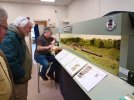
All set up and ready for the public to arrive.

My fellow operator for the weekend, Steve, at the helm doing a spot of shunting - collecting cattle wagons with the 517 train engine from the yard to add to the rest of the cattle train in the Up platform.

A Down passenger train arriving into Modbury with me in charge. Not sure what has my attention in the fiddle yard as the train approaches!!

First of what will later be known as the 45xx class (no. 2161) pauses at the signal box with a Down goods while waiting for Duke "Fowey" to be given the right of way from the Up platform.
Thanks for looking.
Ian
This view shows the old control panel (photo taken at the Loughborough exhibition a few years ago) with the old set of switches.
The revised control panel with the new lever frame. As can probably be seen, the old version had space for some 18 switches (4 of which weren't used but allowed the switches to be spaced and grouped - switches 17 & 18 for example controlled the points in the yard that would have had local hand levers). In replacing with a lever frame, I have taken the opportunity to remove the redundant spaces, this has meant that the switches north of number 7 have all been reassigned, and has also provided an opportunity to swap the numbering of the Down signals (no. 14 was the Down Home, no. 15 was the Down Starter) such that the numbering is now correctly left to right (so now the Down Home is no. 13, and the Down Starter is no. 12).
Needless to say that this extra work within the control panel was not without issue!! I managed to break off one of the pins of a relay which meant replacing said relay, another wire also became detached and took some time to try to work out where and what it had been attached to. Fortunately, I had fully documented the wiring within the panel so all was not lost!
A closer look at the new control panel, the LED and Push-to-break switch on the right of the panel (which were on the old panel too) show if power is still being supplied to the track in advance of the Advanced Starter or Shunt Ahead Signals - the way my wiring works is that the signals provide track power, it does this by means of a pair of relays. When the signal is released, power is provided to the first relay which switches in track power in Rear of the signal, the other half of the relay provides power to a second relay which switches in track power in Advance of the signal. If the signal is restored after the train has passed, the track power in Rear of the signal is cut (because the first relay is deactivated), but the track power provided by the second relay in Advance of the signal is maintained by a "stay alive" circuit. This LED indicates that track power is still being provided by the relevant second relay, the button switch provides a means to break the "stay alive" circuit. I hope that makes sense!!
Now that the revised control panel has been installed, I intend to play trains for a few days to fully ensure that everything I have changed works the way that it should (I have tested it all and it seems ok), because Modbury's next exhibition is at the Macclesfield show on the 11/12th April.
As mentioned at the top of this post, Modbury was out at the Bournemouth exhibition in mid-February, a very nice exhibition and we were well looked after. Below are a few photos from the weekend :
All set up and ready for the public to arrive.
My fellow operator for the weekend, Steve, at the helm doing a spot of shunting - collecting cattle wagons with the 517 train engine from the yard to add to the rest of the cattle train in the Up platform.
A Down passenger train arriving into Modbury with me in charge. Not sure what has my attention in the fiddle yard as the train approaches!!
First of what will later be known as the 45xx class (no. 2161) pauses at the signal box with a Down goods while waiting for Duke "Fowey" to be given the right of way from the Up platform.
Thanks for looking.
Ian
Attachments
Joe's Garage
Western Thunderer
That is a very railway like lever frame Ian, adds to the authenticity of the layout.
Thank you for sharing this
Julian
Thank you for sharing this
Julian
Ian Smith
Western Thunderer
This weekend (11th/12th April), Modbury will be one of the attractions at the Macclesfield Model Railway Exhibition being held for the first time at the Kings School Sports Centre, Alderley Road, Macclesfield, SK10 4RH (Exhibition). It looks like it will be a very nice exhibition with some 25 layouts in attendance and trade support too.
A few photos of Modbury :


A few photos of Modbury :
")
Joe's Garage
Western Thunderer
I am not sure Ian if you have ever mentioned the date Modbury is supposed to be set but I can see it is definitely early 1900s with the livery of the locos and stock, and the old baulk style track.
I was wondering when did the GWR stop using the Indian Red frames on the locos? My reason behind the question is based on my interest in the Abbotsbury branch and the allocation of the 517 class, specifically No. 202. Sorry to steal the thread but last week I succumbed to the temptation by purchasing the new Dapol model of 202, with Indian Red frames. I was trying not to do this having seen the pre release photos which really were very orange, but when this model came up at such a good price, I couldn't say no!
No. 202 was running on the branch in the first few years of the 20th century so it would have this livery, Brian Jackson's book says sometime after 1905.
Now I need 3 or 4 four wheeler carriages to make up the typical pre auto train diagrams.
I definitely have no excuse to start on a model of Abbottsbury.
All the best
Julian
Ian Smith
Western Thunderer
Julian,I was wondering when did the GWR stop using the Indian Red frames on the locos?
My understanding is that the frames started to be painted black sometime in 1906. Obviously that wouldn't happen overnight, so I would imagine that some Indian Red framed locos could still be seen at least a couple of years after that.
I have built a model of 2161 (the first 45xx) which I've given black frames which emerged from the shops in late 1906 (technically a few months too late for my supposed summer 1906 but I have a modellers licence and have deployed it on this occasion) - what I did find interesting was that I have seen other models of 2161 in the full Indian Red framed livery (in 7mm I possibly (perhaps Lee Marsh models???))
Ian