Rewanui (1940 NZR in 1:64)

Responding to a suggestion from SimonD that a model deserved its own thread...

Rewanui is a work in progress that features elsewhere from time to time. First and foremost it's a place where I get to try stuff. So this thread is likely to be occasional and eclectic, but will all be based around this South Island West Coast NZ coal branch in 1940.

An interesting prototype:
  • 3' 6" Narrow gauge
  • A Fell incline (centre rail used for braking only in this case)
  • No road access
  • Once a day there are two engines in the yard.
As a result there are frequent short trains of interesting vehicles, including a relatively intense passenger service. The morning miner's train is 7 cars. This was the last duty for vehicles before being written off, so they have character. But there is a lot known. Numerous images, drawings and file archives are accessible, even some film.

It's 100% scratchbuilt other than rail, motors and gears etc. But I'm a small manufacturer, so scratchbuilt also means that I'm building my own kits. Very little is completely finished, but it's progressing quite fast now.

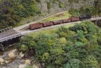
The trackwork is simple as more or less just the station is modelled, with virtually no compression. Trains come up the incline from a fiddle yard. Empties are shunted over a back shunt bridge to the offscene bins (also the fiddle yard). In this way full/empty exchange is achieved invisibly. It's really a shunting plank. I've nowhere to put it, so the layout only actually runs at exhibitions. That's OK as my attention span is short and I have a lot of other things on the go.

Track is NMRA compliant, but wheels are a bit of an orphan profile that is not too far over scale. This is an accident of history that I've no intention of changing at this point. If I had time over, I would tighten the track standard, but I can live (just) with wide flangeways.

So to kick this off, one of the big issues was autocoupling. The layout is deliberately high and I wanted some action to be seen through the trees. That can only work with reliable autocoupling. NZR used 'Norwegian' choppers, so that was a hurdle. The video from a year or two ago shows how this turned out as well as showing the control system which is a custom application running as a webserver on top of DCC-Ex. The schematic shows how uncoupling works. In reality coupler centring is no problem as with hands free uncoupling the couplers stay centred (but they are magnetically centred, as I'm a belt and braces type).

Finally there is an image of some actual modelling.


uncoupler mechanism.JPG
 

Attachments

  • Wa217-on-backshunt.jpg
    Wa217-on-backshunt.jpg
    608.8 KB · Views: 43
Lawrence,

what is the purpose of the smaller (6x6) magnet in the rotating/inverting uncoupler?

cheers
Simon
The geometry of the couplers is such that the hook needs to be pushed up (obviously), but it can (as with the prototype) go over centre, so the other magnet is to pull it down. It probably increases the overall magnetic field in a useful way as well.

In practice this is actually a little painful. Early thoughts were that with the hook up you could propel and place a vehicle, but that's not really needed or practically reliable (and you're stuck with a raised hook). There is no practical advantage to a raised hook, and it can be problematic if there is no available uncoupler to propel the vehicle over. My more recent coupler castings for personal use have departed a little from scale in that a) the uncoupled hook is prevented from dropping quite as low as the real thing can. This makes coupling up a little more reliable through improved geometry, and b) there's also a little lug that prevents the hook from going over centre. Performance was close to 100%, but without those mods it sometimes took a couple of goes, or you needed to couple with a bump to pop the hook down.
 

40057

Western Thunderer
Hi Lawrence

The landscaping, water and vegetation looks fantastic. I have never been to NZ, but your tree ferns look exactly like those in woodland gardens on the west coast in Britain. Am I correct in identifying some of your trees as Nothofagus? (Again, quite widely grown in the UK in gardens and parkland.)

Martin
Thanks Martin

When I was doing undergraduate botany they were. These days I think they've played with the taxonomy a bit.

The plant cover in the area is temperate rain forest. Plenty of ferns and moss with epiphytes growing on the tress. Mostly southern beech (Nothofagus) but podocarps as well (which are harder to model). The line was opened in 1910, and as you might expect the forest in and around the station was removed. So by 1940, vegetation would be 30 odd years of regrowth.
 

40057

Western Thunderer
Thanks Martin

When I was doing undergraduate botany they were. These days I think they've played with the taxonomy a bit.

The plant cover in the area is temperate rain forest. Plenty of ferns and moss with epiphytes growing on the tress. Mostly southern beech (Nothofagus) but podocarps as well (which are harder to model). The line was opened in 1910, and as you might expect the forest in and around the station was removed. So by 1940, vegetation would be 30 odd years of regrowth.
Hi Lawrence

My first degree was botany too (admittedly now a very long time ago). But I could immediately see your vegetation was beautifully modelled by someone who had closely observed the real thing.

Martin
 
This indifferent copy of a 1954 J Joyce image from atop the water vat sums up most features of the layout , which is, I suppose a branch line terminus.

Everything on this side of the Seven Mile Creek will be modelled. The private party tub trestle and bins in the background on the left will not.

This image is probably of an excursion. While busy, the station did not generally get quite this much passenger traffic.

Features:
  • The station master's house is out of frame on the left, but his garden can be seen.
  • The dark shed is, I believe, accommodation for some junior staffer and pretty grim it must have been.
  • The station building is obvious, and detached behind it the gentlemen's convenience and lamp room.
  • The bridge in the background is the only extant feature in this image. It is a railway bridge (but without track), and provided dray access to the mines which are much further up the valley. In reality it was primarily pedestrian access to the hoist that took miners to the mines above.
  • Locomotives are We class 4-6-4T. They started life as Sharp Stewart built class B 4-8-0 tender engines. Note the cut outs in the cowcatchers to clear the centre rail on the incline. In 1940 there were only 2 of these, 377 and 198. Both are shown here, though 198 had been renumbered 376 by this time.
  • The first vehicle in both trains is a 4 wheel Fell van. The guard was obliged to ride in this van on the incline and operate the gripper brake that acted on the centre rail. There were quite a few rules regarding the order of vehicles in the train. These related to safety and braking, but on the layout merely serve to add operational interest.
  • Many of the cars have elevated (clerestory) roofs. Open verandahs were a feature of NZ cars of the time.
  • The shed over the track in the background is for the 'ambulance'. In the event of injury to a miner, and if a train were unavailable, the ambulance (a modified wagon) could be worked by gravity to carry them to aid.
  • The single wagon on the ambulance road appears in quite a few images. It's a side tip muck wagon (I think) and was presumably used by the way and works dept to help clear the frequent slips on the line.
  • The bank on the right forms the backdrop for the layout.
There's an awful lot going on for what, area-wise, is a tiny branch station. We try to run the real timetable (although anachronistically we run a 1950s version as the workings are just slightly more interesting). Partly, this is all just part of the fun, but practically, running the actual timetable is an easy way to avoid shunting yourself to gridlock (though that still happens sometimes).

Rewanui 21-11-54 We376-377 JJoyce.jpg
 
Furious posting here is possible as I'm catching the forum up with modelling from the last few years. Actual progress is not nearly so quick.

As a WR ex-pat, I'm aware that NZR engines are an acquired taste. Bear with it as you'll grow to love them.

Engines on the line were restricted to those modified to deal with the centre rail. In 1940 that meant cutaway cowcatchers, modified brake linkages and an additional steam actuated gripper brake that acted on the centre rail.

This thread was prompted by Simond's reaction to this engine (Wa217), and somebody else asked how you set about designing a kit for such a thing.

I'm not going to attempt an exhaustive dissertation on either the engine build or kit design here, but some comments:

NZR modellers are fortunate as almost all the drawings ever done seem to still exist, there's a pretty good photo record and government and enthusiast archives have done a good job of preserving records. You still have to dig stuff up, but it is generally possible.

I've no formal engineering training and I'm entirely self taught. Fortunate though to be learning at the beginning of the information age so things like CAD are second nature, whereas draughting is not. This stuff is all pretty easy with 30-40 odd years of experience, but it was not always like that.

Even without much experience it is pretty easy to lay out parts and to get them etched. When it comes to building something though, there is a world of difference between soldering together 4 cab sides and simply folding up an assembly. The difference is design, and it is what separates a good kit from an average one. The other key aspect is realisation. The methods and tolerances used need to achieve an appropriate fit. Experience teaches you things, so much of what I now do was learned the hard way earlier. The principle is the same though. I design Mk1 and build it. Anything that I find tricky to do clearly needs to be reworked so that it is easier. Easier means more enjoyment and a far better chance of a clean accurate job.

Digital is an an enormous advance. It's accurate, and cut/paste/copy/mirror/undo save a huge amount of time. The etchings obviously come from CAD, but so do all of the castings. These come from 3D prints in a castable resin, supplied to a contractor who does the investment and casting. Removing the wax moulding step has a couple of advantages. Firstly shrinkage and distortion largely occurs in the waxing. Secondly parts that don't need moulding can be significantly more complex and detailed. They can also be thin walled which makes them easier to use. The Wa chimney, domes and cylinders have a wall thickness of 0.5-0.7mm.

So, yes, I'm proud of the finished Wa, but most of that is down to design rather than assembly.

Wa-217-primed-1.jpg

So with the etchings it's mostly about designing to make things fold, self jig etc. to simplify assembly. As can be seen in the image above cabs are designed so that glazing is inserted into a slot within the cab side. Perfect glazing in seconds. I've got similar tricks for a host of other areas that are problematic. Some of these I came up with myself (to have them pinched by others), others I've pinched in return.

Wa217-3-300124.jpg
The 3 Greymouth Was were all rather different. Three distinct motions for starters. Wa217 shown had the underslung crosshead on a single slidebar (slide valve), 289 had the cross head slung under twin slidebars (slide valve) and 137 had piston valve cylinders and a crosshead fitted between a pair of slidebars. Most of the motion differed accordingly. On top of that just about every detail part varied. Great for the Rewanui modeller, problematic for the kit designer.
Below is the cylinder/slidebar/motion bracket casting for 217. It needs minimal clean up, and as a single piece avoids the hassles and risks of assembling from individual parts. Casting quality of late has improved quite a bit even over that shown. The jewellery industry has embraced digital design and 3D, which has pushed casting to keep up.
Casting-2-sml-130223.jpg

electrical-parts1.jpg
This is a recent sprue of electrical parts. The small junction boxes (1.2mm dia) have short spigots rather than needing drilled holes. This allows 0.4mm tubing to be used for the conduit. This is WAY quicker and easier than trying to drill the fittings and use wire. The embossed text on the generator is almost legible.
 

Osgood

Western Thunderer
....... As can be seen in the image above cabs are designed so that glazing is inserted into a slot within the cab side. Perfect glazing in seconds.
....

From the photo it looks like you have double-skinned the cab front in order to create a hidden pocket for the glazing material?
 
From the photo it looks like you have double-skinned the cab front in order to create a hidden pocket for the glazing material?
Yes Tony. Typically the cab structure folds up out of full thickness metal. The join is somewhere convenient, NOT on a corner. That gives an easily achievable square foundation. The visible detail is a skin, half etched generally with detail. The inner structure has holes to allow soldering the skin on from behind. There are 2 minor downsides to this. 1. If you are heavy handed or use too much head the hole locations are visible as slight distortions in the skin. Easily avoided by being quick and sparing (or you could use epoxy I imagine). The other problem is that the internal surfaces need filling if that bothers you. It's pretty hard to see one way or the other to be honest.
 
Top