Rob P's Journey Into Miniature Gear Cutting

Rob Pulham

Western Thunderer
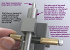
Following on from my "Can anyone tell me who makes or supplies this gearbox?" thread I decided to create a separate thread to share my ongoing journey into making the gear boxes that I have complete with a final drive gear and subsequent explorations with making my own gears and gearboxes.
The original thread is Here

Following the discussion on the other thread, I have started the journey by purchasing a set of Module 0.5 gear cutters and a 2MT arbor from Chronos

cuttersetl-2-655x396.jpg

https://www.chronos.ltd.uk/product/set-of-6-gear-cutters-with-2mt-arbor/

The final drive gears on the two gear boxes are module 0.3 which we concluded was a bit fine for 7mm scale so rather than buying a full set of MOD 0.3 cutters I managed to obtain a single no5 cutter from Gavan Tools in Japan for £16 plus £4 postage to hopefully cut the final drive gears for the gear boxes that I have.

Gavan Tools

This cutter is still on it's way and I have just become a full time carer for a few weeks so this will be a slow burn thread but I will update it as I progress.
 

Rob Pulham

Western Thunderer
Yesterday I checked the despatch email that I had received from Gavan which had a tracking number. Now previously my experiences of tracking items before they reach this country has been a bit sketch but I was pleasantly surprised at seeing all the info below. Unsurprisingly despite buying it from a Japanese supplier, it's actually en-route from China.

1759347568739.png
 

Rob Pulham

Western Thunderer
I checked again this morning and it had got to Stockton on Tees at just after 1am today
1759347690121.png
I was hoping that I might receive it tomorrow, so I was pleasantly surprised to wander downstairs this evening (while taking the rubbish out) to find it had been delivered.

This is it after wiping some of the packing grease off

MOD 0.3 #No5 Gear Cutter.jpg
I messed about with the image contrast so you can better read the detail.

MOD 0.3 #No5 Gear Cutter contrast.jpg

By good fortune today I also found a video where a guy with the same spin indexer as me had made a non standard division plate from some sheet metal. He needed 14 divisions whereas I need 29 for my first foray into gear cutting.
 

simond

Western Thunderer
I guess the loads on the index wheel are relatively light for gear cutting, especially a one-off job, so I wonder if you could either laser-cut MDF (or Trotec) or 3D print a plastic index wheel.

29 is not a convenient number, but the CAD will do it easily enough, and accurately too.
 

Overseer

Western Thunderer
By good fortune today I also found a video where a guy with the same spin indexer as me had made a non standard division plate from some sheet metal. He needed 14 divisions whereas I need 29 for my first foray into gear cutting.
Rob
I don’t want to spoil your fun but dividing plates with 29 divisions are readily available. Vertex make a range of dividing heads and sell spare dividing plates at a reasonable price. This is one of the options available locally here, not sure about UK suppliers - https://www.machineryhouse.com.au/d0015
 

Rob Pulham

Western Thunderer
Rob
I don’t want to spoil your fun but dividing plates with 29 divisions are readily available. Vertex make a range of dividing heads and sell spare dividing plates at a reasonable price. This is one of the options available locally here, not sure about UK suppliers - https://www.machineryhouse.com.au/d0015
Thanks Frazer,
Had I gone a different route and bought a dividing head instead of a spin indexer, that would have been a perfect solution. I like making things but I don't expect or desire to make everything.
As it is, the indexing plates for a spin indexer are much bigger having a 45m hole through the centre.
 

Rob Pulham

Western Thunderer
I guess the loads on the index wheel are relatively light for gear cutting, especially a one-off job, so I wonder if you could either laser-cut MDF (or Trotec) or 3D print a plastic index wheel.

29 is not a convenient number, but the CAD will do it easily enough, and accurately too.
I cannot see why any of those examples wouldn't do the job. I have already drawn it out on cad I just need to measure my own indexing plate to ensure that the holes are the right size for the locking pin and on the correct pitch circle diameter to match the spin indexer.
From a 3D print perspective, I think that PLA would probably be more suitable than resin but of course it does depend on the resin used.

It's good to see the thread generating discussion particularly as I am less than a complete novice when it comes to gear cutting and anything associated with it.
 

Rob Pulham

Western Thunderer
I have been asked if I will do a 'gear cutting 101' for those with little understanding of gearsand gear cutting (I count myself amongst them... ;) ) So I will endeavour to share what I have determined so far.

Gear sizes/measurements come in two flavours (as you might expect) Imperial and Metric. The descriptions for these are:

Involute DP Gear Cutters ( DP standing for Diametral Pitch inch size) These come in two pressure angles 14.5 degrees and 20 degrees

Metric Module (MOD) have a declared pressure angle of 20 degrees.

Each Involute DP or Module set is made up of 8 cutters which perversely, the number for each type is reversed from each other

Gear types.png
View attachment 80194
For the purposes of my journey we are only concerned with the metric MOD types at this point which will be MOD 0.3 for the final drive gears of the 2 Shogun gearboxes that I have and MOD 0.5 for future from scratch gearbox builds.
 

Bob Essex

Western Thunderer
Might I add a little to this thread?

Of the two involute gear pressure angles 20 degrees in the more commonly used, 14.5 degrees is mostly for when heavy loads are placed on the gears, the tooth form being thicker although in truth any pressure angle can be used to suit a particular situation with the cutting tools being generated to match that chosen. Past a certain size gears are cut using shapers and milling machines.

The disc type gear cutters are only really meant to cut 'straight' cut gears i.e. those parallel to the gear shaft axis. If they are used to cut teeth at a helix angle then this needs to be shallow and the wheel narrow. This is because the teeth must (obviously) remain vertical to the axis centre and set at a helix this will twist/rotate from one side to the other. Generally with small size gears hobbing is best as the hob cutter will automatically perform this task at any helix angle and with any number of teeth. So only one hob cutter of a particular tooth size is required to cut gears with any number of teeth, (although you do need both left-hand and right-hand hobs if you want to cut helical spur gears).

Of course unless you are like me you won't want to generate your own tooling and equipment to undertake hobbing, it's a fair old task. However it does allow gears to be produced in quantity much more easily and quickly.

Hope this is of help/interest.

Bob
 
Last edited:

Rob Pulham

Western Thunderer
I guess the loads on the index wheel are relatively light for gear cutting, especially a one-off job, so I wonder if you could either laser-cut MDF (or Trotec) or 3D print a plastic index wheel.

29 is not a convenient number, but the CAD will do it easily enough, and accurately too.
After thinking about Simon's suggestions and updating my CAD model I had a quick look on the bay of e out of curiosity to see how much laser cut steel disks were. I struggled to find what I wanted they were all either much too big or too small.

As occasionally happens with searches, a listing of 130mm diameter by 6mm laser cut acrylic popped up for £4.08 delivered this is the right thickness and a couple of mm oversize on the diameter so I figured that I probably couldn't get anything laser cut with all the holes in and delivered for that price, so I ordered one.
 

Brian McKenzie

Western Thunderer
Hi Rob,

I don't know if your spin indexer has its own clamping mechanism, but I've found it very advantageous to have this feature for gear cutting. I'm then not reliant on whatever indexing method is used for locking the shaft carrying the gear blank. Allows for the use of paper or simply made templates etc.

The brass split cotters, as shown below, are a brilliant but simple way of locking shafts very rigidly - learnt from George H. Thomas articles in "Model Engineer".

S4760002 Gear cutting fixture.jpg


@Bob Essex (post #10) is right on the money about hobbing. This tends to produce higher quality gears than by single-pointing - offering better 'cylindricity', plus the opportunity to re-adjust the PCD marginally, if needed, to fit existing shaft/axle spacings.

Worm wheels are easily hobbed by adjusting the lathe top slide to the helix angle required (then by feeding the cross slide under the hob rotating in the lathe chuck). Hobs are screw cut in silver steel, hardened, then gashed using a Dremel to obtain the cutting edges.

It was Sid Stubbs' article in MRJ #42 that got me started making gears, and that eventually spilled over to designing some for heavy industrial use in wool scours around the world. Ivan Laws' book, "Gears and Gear Cutting" ISBN 0-85242-911-8 is likely the best book on the subject for modellers.

Looking forward to your gears, in a mechanical sense, equaling the finest scenic effects that we see on WT !

-Brian McK.
 

Attachments

  • S4760002 Gear cutting fixture.jpg
    S4760002 Gear cutting fixture.jpg
    233.6 KB · Views: 0

Rob Pulham

Western Thunderer
Hi Brian,

Yes, even thought the dividing plate supplied is a chunky piece of 6mm thick steel, the shaft does have a separate locking screw. You just have to remember to tighten it.
 

Dangerous Davies

Western Thunderer
Rob
+1 for the brass split cotters by GHT. I have used them on several pieces of workshop tooling.
I can recommend “Dviding and Graduating“ by George H Thomas, ISBN 0905100859 which tells you all you need to know about the subject and how to make the equipment to produce divisions of prime numbers.
Keep up the progress reports.
Cheers
Dave
 

Bob Essex

Western Thunderer
I would second @Brian McKenzie recommendation for the Ivan Law book, the best info for the home user by far, complete and concise. One aspect though is 'free hobbing'. I can't say I find it worth using. I have tried it as a simple way to hob, but my success rate had been zero. My experience is that the arbour does need to be geared to the hob cutter otherwise there are malformed gears and often one less gear tooth at best. This is of course because it relies on the cutter 'driving' the blank. I have never tried it with larger tooth forms where it is imperitive that the teeth are gashed first, which to my mind then defeats the object and you might just as well form the gears that way anyway using the relevant tools etc.

I have posted these shots before somewhere, so apologies if you've seen them before, but this is what's possible. My setup uses my Hobbymat lathe with the arbour being driven off the carriage bed gearing through drive shafting. So the arbour is locked rotation wise to the headstock spindle, the reduction matching the gear teeth number required. Different arbours for different sized bores. This is the basics of hobbing. Julia has taken this to a new level with the machine made for the 2mm association by using CNC design and stepper motors etc. so the rotation of blank and cutters is done by programming, really clever stuff well above my pay grade!

RMweb 7mmG 01.jpg

RMweb 7mmG 02.jpg

The tooling mainly uses tool steel given to me by my late father-in-law. Really nice stuff that cut easily. The smaller ones are 1/4" tools and both handed versions in the smaller size for helical spurs. The larger cutter was to offset having to set the arbour at a helix for straight cut spurs. You can of course use machine taps with ordinary screw forms to cut simple worm gears in place of involute tooth hobs, a 'quick & dirty' way suggested by my father-in-law.

RMweb 7mmG 03.jpg

The worms were of course lathe cut, probably the most boring bit of the job, running the carriage back and forth cutting a length and then chopping them up etc. Two sizes 36-1 & 42-1 (0.5 mod & 0.6 mod) to match the fold-up etched gear mounts found in the Connoisseur kits and so forth.

RMweb 7mmG 04.jpg

And of course spur gears in multiple sizes to choice for two-stage bespoke boxes. I did do both straight cut and helical cut versions but found little actual different in use. I guess it might vary depending on the use involved. All 3/16" bore.

RMweb 7mmG 05.jpg

These are just the left overs from those days.

For what Rob wants disc cutters and dividing wheels are certainly the easiest way to go and it's always nice to be able to make things yourself with what equipment you have to work with. I look forward to seeing the end results and the rescue of those nice motor/gearbox units.

Bob
 

Rob Pulham

Western Thunderer
Thanks Bob,

I confess that I had thought of trying a length of M6 x1.0 stud and using an M10 x 1 tap to do just that in order to get the worm and initial wheels. Then I envisioned using the gear cutters to make the spurs through to final drive gears as a starting point things can then be refined as experience grows.

Would you mind taking a few more shots of how your attachment drives off the lathe carriage bed gearing please - I am quite fascinated by all such things

I ordered the Ivan Law book this morning :thumbs:
 

Ian@StEnochs

Western Thunderer
Thanks Bob,

I confess that I had thought of trying a length of M6 x1.0 stud and using an M10 x 1 tap to do just that in order to get the worm and initial wheels. Then I envisioned using the gear cutters to make the spurs through to final drive gears as a starting point things can then be refined as experience grows.

Would you mind taking a few more shots of how your attachment drives off the lathe carriage bed gearing please - I am quite fascinated by all such things

I ordered the Ivan Law book this morning :thumbs:

Rob,

Back in my 4mm days I made worm and wheel gears using an M6 tap. For the gear I mounted the brass blank on an arbour held in the tool post and just plunged it into the rotating tap. Must have been luck as the setup worked and turned out a gear with all the teeth intact. The worms were made from commercial steel M6 screw rod. Because the tooth form was concave the mesh had to be held in a gear box with no sideplay but they worked well and may still do as I sold the models on some time ago.

Ian.
 
Top