Rob's 3D Drawing workbench

MarkR

Western Thunderer
Sorry Mark, I missed this when you posted it back in January. I love it. You may have seen elsewhere that I did a few modifications to it to make it more rigid but it's does everything that I want from it
Hi Rob,
No problem, I watched your lathe modifications with interest, you never know!
Mark
 

Rob Pulham

Western Thunderer
I haven't had much time for physical modelling this week so I have spend what time I have had doing a bit more drawing in Fusion.

These are an assortment of parts for the D2 test build when I get to it.

LNER D2 front Sandbox.PNG
LNER D2 front Sandbox 2.PNG
LNER D2 front Sandbox 1.PNG

Front Sandbox, most of it will be hidden behind the front steps but some of it is visible.

Brake shoes, to take away the risk of shorts.

LNER D2 Brake Shoe 1.png
LNER D2 Brake Shoe 2.png


Finally for now, is the reverser for the cab

7mm Scale LNER D2 Reverser Finished.png
7mm Scale LNER D2 Reverser Finished 2.png
 

Rob Pulham

Western Thunderer
I couldn't resist another embellishment to the reverser.

52202490961_20e63f17ea_b.jpg
 

Rob Pulham

Western Thunderer
And I am most impressed with your 3D drawing skills, I am stopped at 2D drawing this time around.

Michael
You are one up on me then Michael, I can do very basic drawings with Inkscape but I have never really mastered or even become mildly competent with a proper 2D CAD program.
 

Rob Pulham

Western Thunderer
Over on one of the other forums, I was asked for help in the form of how to go about drawing up an NSR lamp post

On the basis of the drawing I had a few ideas of who I might go about it and once I had it cracked I was asked for an explanation of how I had gone about it. I thought I would share it wider as it might help someone at some point. You will have to excuse some of the wording that relates to answering the initial question. I haven't the time at the moment to go through and re write it.

This was the drawing attached to the request for help.

North Staffs Platform Lamp Drawing.jpeg

First, I downloaded Andy's drawing and imported it into Fusion on the front plane. Then as I said previously but repeated here for completeness. Because the drawing had no dimensions, I best guessed that the main part of the post would be around 10 feet tall - I was way out as it's only around 6ft when taken right to the ground!

However, using the 10ft as the basis, I created myself a User Parameter of 1ft/7mm which allowed me to quickly scale the drawing to 7mm to the foot.

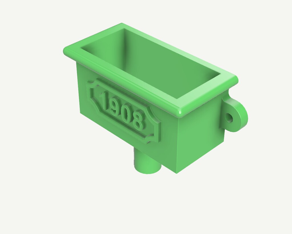
Next, I drew a profile of the lamp base and revolved it.


Then I worked out the middle of the column height wise and created an offset plane.


52278557099_bb0c4ce73b.jpg


Then, I created a sketch on that offset plane and drew the shape for my cut out


I only drew one of the shapes then used the 'create circular pattern' tool to create the other five. As it turned out, initially I had the outer circle slightly under the column sized so when I extruded as a cut it was actually inside the body.


I then, extruded using the symmetrical function and cut command so I was going both up and down to get the cut outs in place all around the column.


Rob Pulham

Western Thunderer
Next, I drew a couple of upright lines on the first sketch to determine the width of the base of the fluted section. Which was 8mm on my overscale drawing. Then I created another offset plane this time at the top of the column/base of the fluted section.


Then, I created a sketch on that plane and drew a circle 8mm in diameter, on the edge of that circle I drew another circle 0.6mm in diameter. Using these as a best guess for the size of the flute. I then used the circular pattern tool to create circle all around the inner circle. this ended up being 42.


Then on the first sketch I drew the profile of the flute.


I extruded this again symmetrically 0.3mm either way, to give me the 0.6mm thickness that I had determined (best guess!!!) was the flute size. Then I filleted the front edges to give me the round flute


Lastly, I used the circular pattern tool again to create the circle of 42.


I even managed to get the render tool to work this morning last night I think that my machine was doing an update in the background and it was running like a dog.
 

Overseer

Western Thunderer
because it's meant to represent something that has been cast I went round and softened some of the edges using the fillet tool

52280532459_9b61cbd28c_b.jpg


52280316048_ec5cf396fd_b.jpg
Rob,
Looks good. Interesting the NSR chose an Egyptian inspired lamp post, but why not. Without seeing a photo I am not certain but I think the recesses in the lower part of the post might be too deep. The inner moulding in the recess also looks a bit big and should return across the top and bottom of the recess like a picture frame.

Certainly easier to draw in 3D and print than trying to machine or carve a lamp post like this.
 

Rob Pulham

Western Thunderer
Rob,
Looks good. Interesting the NSR chose an Egyptian inspired lamp post, but why not. Without seeing a photo I am not certain but I think the recesses in the lower part of the post might be too deep. The inner moulding in the recess also looks a bit big and should return across the top and bottom of the recess like a picture frame.

Certainly easier to draw in 3D and print than trying to machine or carve a lamp post like this.
Hi Fraser,

I only had a drawing to work of so it may well be too deep, it is exaggerated by the magnified images, the inner moulding is only 0.3mm x 0.3mm
I agree that the inset should go all around, I just haven't worked out how to do the top and bottom yet. While typing this, an idea of how to do it has occurred so thank you.

7mm scale NSR Lamp Post -6.PNG

I have also filleted all the edges to take of the sharpness which has made it look a little less deep (to my eyes at least).
 

Rob Pulham

Western Thunderer
A fellow Guild member asked a question on the Gog Forum about rainwater goods and how easy they would be to print.

This piqued my interest and I knocked this up in about 40 minutes last night. It would have been quicker but my broadband was playing up and Fusion crashed a couple of times before I was able to save it.

It's drawn from a photo taken and posted by the Gent who asked the question, so I had no real dimensions to work from. I guesstimated at a scale 1ft x 1ft x 2ft wide with a 3" outlet.

52342592451_08eb3b7937_b.jpg


52343023745_a1a91595ef_b.jpg


52342592521_0965f41d9d_b.jpg
 

Rob Pulham

Western Thunderer
Wow, it's been a while since I last updated this thread. I confess that I have done very little 3D drawing since March mainly things that I intended to machine and modelled them to make working drawings.

I have done so little that when a friend whom I had drawn a number of items in the past asked me to draw up a GNR axle box and horn guide I had no idea how to go about it. Fast forward to a week ago and I decided that after drawing up the side control spring for the 8F that I needed more practice and to relearn how to draw in Fusion beyond the basics. Having recently messed about with gears and I had recreated some gears for my Medley Models Cravens Crane, I decided that I would attempt to draw up a hand crane similar to the one that I built some years ago from a Wagon and Carriage Works kit.

I wanted to go a step further than I have previously where I have built up a design as one entity and create components which would eventually create an assembly.

The W&C kit is designed to make either a wagon mounted mobile crane or a ground/plinth mounted yard crane. I have drawn up parts for both and started to assemble the Yard crane variant first as being the slightly simpler of the two.

It's been a bit of a learning curve but an enjoyable one.

54978505362_d330d2dddd_z.jpg

54979631274_939ac96676_z.jpg

54979384696_15bda4921c_c.jpg

54979682430_bb6c2f5f79_z.jpg
 

Rob Pulham

Western Thunderer
After much more fiddling I arrived at this:

54980641082_67c11e06f5_b.jpg

54981704738_ff233c8b8f_h.jpg

54980641107_8786975b5b_h.jpg

After these were taken I adjusted the angle of the job stay connectors

54981525426_5df648aa2b_c.jpg.

Then I realised that although I had fitted the inner geared roller which is for the brake I hadn't done anything about the brake handle itself. So back to the drawing board...

Plus I still need to work out how to animate it.
 

Rob Pulham

Western Thunderer
I managed to add the handbrake albeit it took a number of tries before I got it jointed in the right place.

A couple of shots of the brake without the central support pillar to make it more visible.

54983283298_cced35dc86_b.jpg

54983393025_21bea72511_b.jpg

Then with it in place.

54982211552_d73d7069a8_b.jpg

54983283313_b8dfebfb8e_h.jpg

It just needs some clevises for the stays and it's complete.
 

simond

Western Thunderer
Rob,

I rather think that the central pillar should be full diameter through the "floor" block, as the pillar is part of, or immovably fixed to, the base. They are probably joined by a taper.

1765888832975.png

this vertical hole will be a foot or so in diameter, maybe more.

there should be a smaller central vertical hole in this bit, with a pin on the column which engages with it,

1765888949556.png

then your crane can rotate on the two widely spaced bearings, and won't fall over!

atb
Simon
 

Rob Pulham

Western Thunderer
Hi Simon,

I see that you mean, and it wouldn't be difficult to join the 'support column' and the 'swivel block' ('xxx' my names for the different elements in the 3D workspace) together*. Whether that would make it easier or harder to 3D print I have no idea.

I confess that my 'idea', if I ever did anything more with it, than draw it up, was that it would have a piece of 2mm rod inserted through the hole to give strength and a solid pivot point. Given that my starting point was looking at my Wagon and Carriage works example and rather basic instructions (which makes no bones about being a generic amalgam of different companies cranes). I accepted from the outset that it was never going to be an accurate representation of any particular prototype.

*I can only assume that the original designer of the W&C kit made it in separate pieces to make casting them in whitemetal easier and I just loosely followed what I can see in my model.

I don't really have a need for a yard crane as my physical modelling is mainly locos and rolling stock. It's more an academic exercise to relearn Fusion and explore components and assemblies while using an example that could potential be made into something if I ultimately desired.

The instructions offer a yard crane option with the square base plate and suggestions of different places where one might cut the side frames. I chose to do that option as being slightly easier to do as a starter while working up to doing a more detailed mobile version once the yard crane was used as the guinea pig.

I am well on with the mobile version design and I will share it when finished but again it won't be of a specific prototype.
 
Top