Tube underground track

JimG

Western Thunderer
There are some fierce curves around Bank and I've no idea why given the depth of the line. One rumour is the li e diverts around the deep vault at the Bank of England. I recall there being several undulations in that area, I presume as the line tries to follow ripples in the blue clay.

I remember working in Broadcasting House in London in what had been the wartime control room and that was three floors down from ground level, and was very close to the Bakerloo Line. You could hear the trains passing in the Control Room. Of course the Bakerloo line would have been there long before Broadcasting House so the building works for BH would have to do the avoiding. :)

Jim.
 

Dan Randall

Western Thunderer
My understanding is that they were not all the same, some sections were wider for the outside of the curve, especially the sharper curves. Those top and bottom sections were tapered to suit. Bit like set track.

More gradual curves used standard sections with spacers between them, any small gaps were filled with caulking

That would make sense Mick, a little like this I would imagine?....

8D898F4E-F1E9-429D-B4EC-8222127C649D.jpeg

I’ll bet they got through some caulking on that job (and this guy should know!). :)):)):))....
19D2D94B-7801-4BD7-ADA8-8F45AE6A13A6.png

Regards

Dan
 

oldravendale

Western Thunderer
There are some fierce curves around Bank and I've no idea why given the depth of the line. One rumour is the li e diverts around the deep vault at the Bank of England. I recall there being several undulations in that area, I presume as the line tries to follow ripples in the blue clay.
.

As a slight diversion - apologies in advance - the curves around the Bastille foundations on the Paris Metro are very tight. The rubber wheeled stock makes an ear splitting racket!

Brian
 

mickoo

Western Thunderer

That would make sense Mick, a little like this I would imagine?....

View attachment 129695

I’ll bet they got through some caulking on that job (and this guy should know!). :)):)):))....
View attachment 129701

Regards

Dan
That's an access tunnel during refurbishment, the floor would be flat and level with the second line of panel joints above the base. The next section is sloped and would be a set of stairs (it's not steep or long enough for an escalator) up to the next level which is also flat; beyond that it looks to rise on a lesser grade.
 

Yorkshire Dave

Western Thunderer
That's an access tunnel during refurbishment, the floor would be flat and level with the second line of panel joints above the base. The next section is sloped and would be a set of stairs (it's not steep or long enough for an escalator) up to the next level which is also flat; beyond that it looks to rise on a lesser grade.

It's also not a large enough diameter for an escalator.
 

Yorkshire Dave

Western Thunderer
More gradual curves used standard sections with spacers between them, any small gaps were filled with caulking, but, as Peter noted, most deep bore tubes followed the blue clay seam under London so water ingress is minimal.

There are some fierce curves around Bank and I've no idea why given the depth of the line. One rumour is the li e diverts around the deep vault at the Bank of England. I recall there being several undulations in that area, I presume as the line tries to follow ripples in the blue clay.

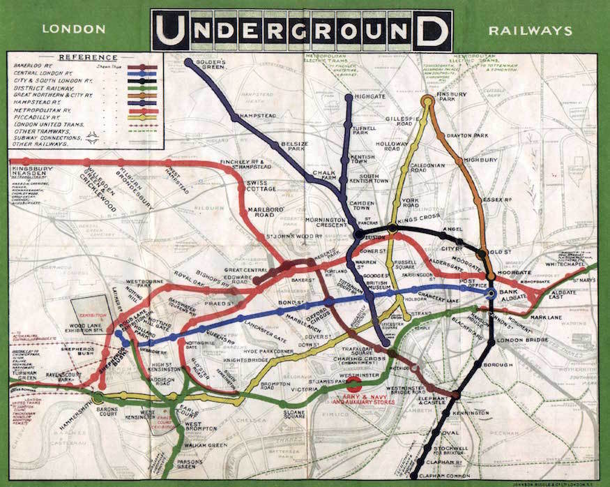
If you find a non-diagrammatic tube map you'll find the original lines follow the streets which would account for sharp curves. This being due to the buildings above as they owned the ground below. They also tended to follow the streets for ease of construction.

1908.jpg


The undulations will follow the clay level as suggested and any other existing obstacle at that level (sewers, enclosed rivers). Undulations were also built in either side of a station to assist with acceleration and deceleration.

On the subject of stations this illustration (from the book I mentioned earlier) shows how some of the early stations and some running tunnels were originally arranged to ensure they remained within the public street boundaries (unless they were granted a wayleave by the building owners to tunnel under the building). It's only the later station tunnels which were built at the same depth to facilitate cross platform interchange. And of course as alluded to earlier in this thread some of the City and South London (Bank branch notably) stations had island platforms in large bore tunnels. These were latterly rebuilt into single tunnels as they became dangerous due to increased passenger numbers and platform capacity.

Tube 4.jpg
 

Lancastrian

Western Thunderer
I remember working in Broadcasting House in London in what had been the wartime control room and that was three floors down from ground level, and was very close to the Bakerloo Line. You could hear the trains passing in the Control Room. Of course the Bakerloo line would have been there long before Broadcasting House so the building works for BH would have to do the avoiding. :)

Jim.

Jim,

Our TV News inject studio to TVC was down there too. Many a time we had to stop a recording as a train rumbled by. Not possible for live DTL's though. As it was serviced from TVC, I had a few regular visits to adjust/fix/maintain the vision and lighting equipment.

Ian
 

Chris Veitch

Western Thunderer
If you find a non-diagrammatic tube map you'll find the original lines follow the streets which would account for sharp curves. This being due to the buildings above as they owned the ground below. They also tended to follow the streets for ease of construction.
View attachment 129713
I've just started reading The Subterranean Railway by Christian Wolmar on the back of this thread - as one who visits London rarely and uses the Tube even less so, it's mostly a fascinating curiosity to me. It seems a shame that it's been largely ignored by modellers over the years and has only recently received much attention (although being mostly invisible may also have influenced this).

Wolmar's book points out that the northern half of London was well served by Tube lines because the ownership of large areas by aristocratic landowners of influence meant that tunnelling was the only viable alternative because of the high land values and difficulty in obtaining consent - he argues that the cheaper land (and less influential owners) south of the Thames meant that surface lines could be built there economically.
 

oldravendale

Western Thunderer
Another minor diversion......Who remembers the April 1st article in Railway Modeller, probably forty or so years ago, about the individual who had built the complete tube network under his floorboards? A masterful piece of railway spoofery for the cognoscenti and on a par with Cliff Mitchelmore's Spaghetti Tree which I've just found on youtube:

Apologies, Tim. This thread is really so interesting that I feel guilty for spoiling it.

Brian
 
Last edited:

Peter Insole

Western Thunderer
Those superb illustrations supplied by Yorkshire Dave show track as originally laid, and don't show the concrete infill set partly up the tunnel lining above sleeper level.

This feature was apparently applied as an insulator by the LER when they discovered that traction current had a tendency of straying to the cast iron segments.

I have an important picture commission, plus a couple more most desirable to do, but cannot start on any of them without at least one visit to the LT Museum, Acton Depot for primary reference sketching and drawing. They were usually a bit reluctant to admit individuals under normal circumstances, but now there will be strict rules until goodness knows when? All of which is doubly frustrating: They have quite a collection of tunnel segments and complete sections that could be measured up for this project.

Do we (fellow WT'ers) have any friends or contacts on the inside maybe?

My old ones are out of date now!

Pete.
 

Tim Watson

Western Thunderer
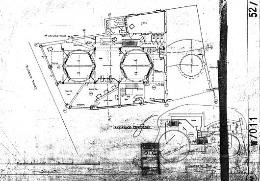
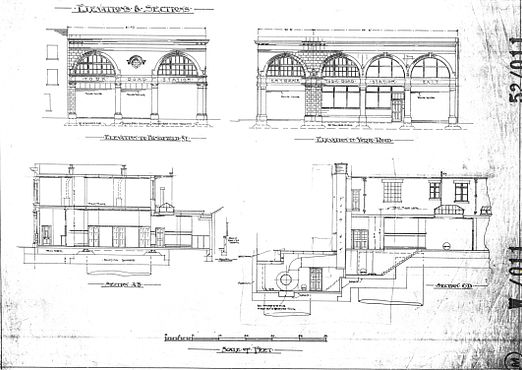
This project is taking on a life of its own (there is a parallel thread on RMWeb). We now have better copies of the elevation and plan drawings (I can forward PDFs to anyone if they would like them).


I have become VERY familiar with this building over the last few days. As my info has increased, so the accuracy of the structure has moved on to a new level - literally. This might have been a relatively quick project; it isn’t now, but then that summarises the CF ethos.

Tim
 

cbrailways

Western Thunderer
Anyone know what the space between rings is? We are roughing out prototypes - laser cut or 3D printed?

Thanks
Tim
Tim. I have seen various references to the segments being 23ins wide. Not sure if that is an actual true reflection though as there were many types of cast iron segments.

However, looking at various photographs there appear to be about 1 1/2 segments to each sleeper spacing. Sleepers are usually spaced around 2ft 6ins apart so the 23ins segment width looks about right, but really only a guess at the moment.
 
Last edited:

mickoo

Western Thunderer
If you find a non-diagrammatic tube map you'll find the original lines follow the streets which would account for sharp curves. This being due to the buildings above as they owned the ground below. They also tended to follow the streets for ease of construction.

1908.jpg


The undulations will follow the clay level as suggested and any other existing obstacle at that level (sewers, enclosed rivers). Undulations were also built in either side of a station to assist with acceleration and deceleration.

On the subject of stations this illustration (from the book I mentioned earlier) shows how some of the early stations and some running tunnels were originally arranged to ensure they remained within the public street boundaries (unless they were granted a wayleave by the building owners to tunnel under the building). It's only the later station tunnels which were built at the same depth to facilitate cross platform interchange. And of course as alluded to earlier in this thread some of the City and South London (Bank branch notably) stations had island platforms in large bore tunnels. These were latterly rebuilt into single tunnels as they became dangerous due to increased passenger numbers and platform capacity.

View attachment 129713
I knew the cut and cover surface stock lines followed the streets, I wasn't aware that the deep bore ones did the same, but it makes sense if the land owners where trying to extract rates and monies for activities below their properties. One does have to question how deep their rights go :eek: there must be a cut off depth where they can no longer claim ownership.

I also wonder if there an element of fear of vibration, subsidence and property damage that also forced building owners to bar lines from beneath their buildings.
 
Top