V2 4 wheel parcel van1/32 and G3

michael mott

Western Thunderer
John, thanks, Jan, your term "Box of Frustrated Disinterest" made me laugh My term is "Shelves and Drawers and Cupboards full of Tests"

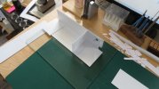
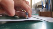
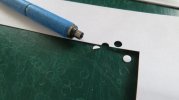
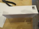
A new beginning, on the 1/32nd van this first pic shows the corners punched out after following the Jenkinson method of opening up the fret, this is .010" printable cardstock. by working this way it is much faster than having to pick out the round punching that fills the punch, the time to cut this out fully was about 1 1/2 hours, then I used the MEK to glue it to some .020" sheet the door window will be cut after the fret has fully cured overnight. I can See why Jenkinson liked to work in Batches, but my stiff neck will only take so much punishment.

IMG_4620x1024.jpg
It was also a revelation upon rereading his book that he likes to leave the ends removable at least until after the painting, so I am going to follow his method of assembly with the difference that I will make the ends in the same way as the test end that I first made as an assembly. and regarding the "sides proper" I will add a bevel to the bottom of the box to create a larger bonding edge that the ones that Jenkinson illustrates.

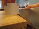
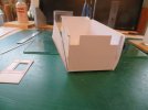
Assembling the basic box. all the parts are cut snapped and planed on the edges to give square gluing surfaces. The inner ends still need their window clearance openings cut before assembly.

IMG_4621x1024.jpg
And so it goes.

Michael
 

Jon Nazareth

Western Thunderer
Michael
I've just found this thread, very, very interesting. Can you describe your punches for me, please?

Jon
 
1/32

michael mott

Western Thunderer
Hi Jon
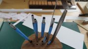
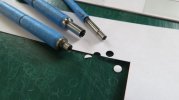
Thanks for the interest. the punches are really simple to make out of silver steel or Drill rod as it is called on this side of the pond. I suppose one could also use old broken drill bits.
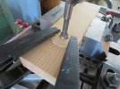
however the method that I have been using is to use a diameter that is larger than the punch that I need and use the appropriate centre drill to begin then drill out the bore to 15 -20 thou smaller than the finished diameter of the punch. Then turn down the diameter until till it is the diameter that I need. I use a bit of 1200 wet and dry to polish up the inside and the outside which because of the right centre drill gives a bevel edge that is sharp enough for this purpose, and then I heat the punch end about 3/4 inch up from the tip of the punch to cherry red and let the heat transfer down to the cutting edge and when it is red quench it in some vegetable oil. re-polish I have not found the need to temper these punches. They don't seem to suffer much in the way of wear when used on the normal cutting mats.
IMG_4625x1024.jpg

IMG_4626x1024.jpg

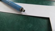
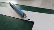
after punching a full hole the punching needs to be removed right away, because the depth is not deep.

IMG_4627x1024.jpg

I use a small tool that I also use to catch small parts when parting off on the lathe.

IMG_4628x1024.jpg

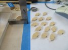
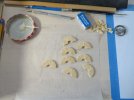
the reason for cutting out the rounded corners afterwards is because it is easier to be more accurate positioning the punch. The blue masking tape simple makes the punch less slippery to hold. and there is no need to interrupt the flow because the half moon simply drops out 99% of the time.

IMG_4629x1024.jpg

last an assortment used for the sides.

IMG_4630x1024.jpg

I hope this helps.

Michael
 

Jon Nazareth

Western Thunderer
Michael
Thank you very much for taking the trouble to explain and show your punches. One last question, I take it that the finished wall thickness of the punch is something in the region of 7.5 - 10 thou. Is that right?
I've ordered a copy of the book by David Jenkinson to see how he goes about making his carriages. I thought that the price was quite reasonable compared to some that were 'How Much!!'

Jon
 

michael mott

Western Thunderer
Hi Jon, yes you are correct regarding the wall thickness. It does punch out the .015 thickness styrene but only after the removal of the rest of the opening following Jenkinson's method. what I do like about using the punches though is keeping the fret flat on the table rather than lifting it up to file the corners. The thing I like most about using the printable card and cover stock is that there doesn't seem to be the same issue of the bur being pushed up on the edges that need to be scraped away. Jenkinson's book is a great resource for any carriage building. Yes the price of some of those copies seemed a bit unrealistic.

Michael
 

michael mott

Western Thunderer
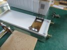
Pressing on with the parcel van after gluing up the "basic Box" I bevelled the bottom edge to the correct angle by measuring it on the drawing, then using a protractor marked the angle in pencil to act as a guide for holding the finely set block plane, a couple of shaves did the trick.

IMG_4632x1024.jpg

IMG_4633x1024.jpg

Then added the horizontal strips before gluing on the sides.

IMG_4635x1024.jpg

By adding the bevel it makes for a much stronger lower joint in my view.

I also have adopted the method of shaping a roof base using wood, I did not have a large enough piece of jellutong (a wonderful wood) for the section but did have a large enough piece of Yellow Cedar which is almost as good for carving and shaping. it still needs a bit of narrowing and height reduction to drop in between the sides,

IMG_4639x1024.jpg
I have found that by drilling a hole in the centre and cutting through the diagonals from the corner to the centre hole first then a light score along the window opening allows for an easy snap out of the waste piece.

IMG_4646x1024.jpg
The next tasks are to curve the ends, and to make the guards look out sections after finishing the roofs.

IMG_4649x1024.jpg

Michael
 

michael mott

Western Thunderer
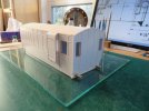
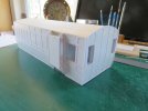
Stumbling along with the guards look outs (I cannot remember the proper name) it was a case of figuring it out as I went along, after fitting the roof and setting up the guards end wall. The first plan was to set up the fret inside the side walls so I used a piece of the cardstock to get the proper setback..... well that went out the window pretty quickly.


IMG_4659x1024.jpg
It looked nice while it lasted, but I needed to get the top and bottom sheeting set up as well, so decided I would overlay the card stock after getting the support right.
IMG_4660x1024.jpg

I shaped a bit of .188" styrene on one edge enough for 4 pieces for the tops of the two vans. I used the block plane and a sanding stick to get very close.
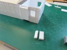
IMG_4664x1024.jpg

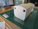
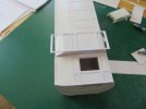
And then after gluing the top and the bottom bits in, I cleaned up the whole thing Sanding towards the centre so as to not damage the card stock on the sides. I needed to develop the fret top and bottom in order to make the fret appear to line up when looking straight on the side. I used the simple method of marking a tally strip and transferring to the fret sheet, after it was cut I glued it from the centre out.
IMG_4665x1024.jpg
I noticed that the tumble-homes are a bit shallower that on the drawing something to work out going forward.

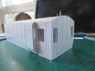
IMG_4666x1024.jpg

IMG_4668x1024.jpg

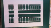
Overall I am happy with the progress, knowing that practice will improve things as I become more clear about the processes.

Michael
 

michael mott

Western Thunderer
Ducket reworked, and a start on the under-frame a bit of a hybrid combination of Davids methodology and my own. Still have to make the mounting plates for the buffer housings they will be styrene with some Grant Line nuts
IMG_4674x1024.jpg
The ducket is a little proud at the bottom, definitely something to improve upon going forward. and t'other end.

IMG_4676x1024.jpg

I am looking into the best glue substitute for Evo-stick which is what David Jenkinson uses for gluing styrene to the wood roofs.

Michael
 

simond

Western Thunderer
Michael,

I followed some of David AJ’s philosophies, and even bought profiled wood roof blanks from the chap he recommended, but I didn’t stick plasticard to them, I used card or good quality art paper, stuck on with PVA. I then stiffened the edges with cyano, fitted any vents or tank panels, and oversprayed with white car primer, followed by weathering to taste.

I may be fooling myself, but the texture seems better than the dead smooth of the plasticard.
 

JimG

Western Thunderer
I am looking into the best glue substitute for Evo-stick which is what David Jenkinson uses for gluing styrene to the wood roofs.

I remember using Evostick to join dissimilar materials forty or more years ago when David Jenkinson wrote his book. I remember diluting it with Mekpak to join Plastikard to wood and it worked well probably because Evostik was quite flexible and allowed for some differential expansion between the materials. But I think they changed the makeup of the original glue because of its popularity with glue sniffers and when I tried to use it in the same way some years later I found that it would not work as it had done.

Because of that I changed the way I made coach roofs and used styrene throughout, making an armature from styrene formers and stringers - a bit like balsa aircraft kit wings - then building up the roof layers with thin styrene sheet held in a curved former to get the correct shape. I've still got these roofs around and they are still holding together very well. :)

Jim.

PS It was actually a series of articles by David Jenkinson in the Railway Modeller during the 70s which, later, were made into the book.
 

michael mott

Western Thunderer
Simon and Jim Thank you both for the feedback. Simon I do like what you have done and it will in all probability be the way that I will go. Jim I too have in the past done as you have done with the forms and stringers it is a lot of work. On a larger scale that would be the method I would use, There being more opportunity to fully detail the interior. for these smaller scales (I know it is huge compared to 2mm stuff) but I am used to modelling 1/24 and up. 1/32 is pushing the limits of all sorts of detail for me. 7mm will be a real challenge!

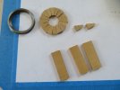
Today I made a start on the wheel centres. The first picture shows the original start with marking out with pencil on a piece of Castello boxwood.

IMG_4677x1024.jpg

The second picture shows some yellow Cedar which was cut using short cuts of the end of a strip using a small custom Mitre box with the length of the rectangular bits cut first then turned sideways and the 11.25 degree cut the the block flipped to cut the opposite side of the wedges. These will get glued up first in pairs then the pairs will get glued up then the quarters to form the blanks for final shaping to fit into the rims. The yellow cedar will take the teak stain better than the Castello. All the cutting was done with the exacto razor back saw.

IMG_4678x1024.jpg
 

michael mott

Western Thunderer
The wheels
pairs of pairs glued
IMG_4679x1024.jpg

Checking for 90 degrees

IMG_4680x1024.jpg

quarters glued

IMG_4681x1024.jpg

IMG_4683x1024.jpg

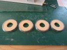
sanded flat then glued and the centre cleaned up with a forstner bit

IMG_4687x1024.jpg

ready for sizing to the tyres

IMG_4688x1024.jpg
I used the same mandrel that i used to hold the tyres ensuring the correct diameter.

IMG_4692x1024.jpg

ready to clean up and fit

IMG_4689x1024.jpg

first fitting some work still needs to be done to thin the a little for the retaining ring and for the hub and its ring,

IMG_4693x1024.jpg

IMG_4693x1024.jpg

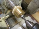
also machined up the buffers out of a scrap of steel that turned out to be free machining what a joy that was. .375 one pass to the finished diameter of the shaft at .085"

happy with the days effort.

Michael
 

michael mott

Western Thunderer
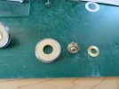
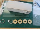
A bit more lathe work today. I decided to make the hubs from a series of discs bymachining the requred diameters and then parting them off. It was the easiest way to ensure that all the diameters and depths were the same then all soldered to a piece of 3/16 brass and then bored and reamed 1/8th
IMG_4694x1024.jpg

IMG_4695x1024.jpg

Then the lot was test assembled
one pair has all the blackening done to get a sense of what I am aiming for.

IMG_4698x1024.jpg
IMG_4700x1024.jpg

and a close up which shows off the segmented section clearly with the pantone marker for colouring the cedar. Once all the parts are finally glued together I will drill the holes for the rivets. and add those.

IMG_4699x1024.jpg

Time for supper.

Michael
 

michael mott

Western Thunderer
worked on the W irons and set them up using the standard method it seems, this helped to ensure that they were stable.

I printed up a sheet on label stock then cut them out with the jewellers saw.

IMG_4713x1024.jpg
then after making a test bend to make sure that I had the bend position correct, I folded them up. and after a minute in some acetone lifted off the print.

IMG_4714x1024.jpg
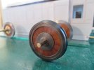
The wheels are all glued up and the W iron are attached with some 1/72 machine screws to the under-frame and the screws pentrate through the floor of the coach box to hold the lot together.

IMG_4722x1024.jpg

Next up the axleboxes need to be made.

IMG_4723x1024.jpg

Michael
 
Top