Yorky D's Küchentisch - Jonny half-a-job...

Rob Pulham

Western Thunderer
I have a couple of Mashima 1428 motors and Branchlines gearboxes in with mine which probably gives an idea as to how long I have had the kit.
 

Yorkshire Dave

Western Thunderer
The NER ES1 instructions include (to me) a scant paragraph relating to the pantograph - in short there are four options...

1. Build up etches as a dummy pantograph in raised position
2. Build up etches as a dummy pantograph in lowered position
3. Use a non-prototypical HO Sommerfeldt operating version
4. Make up etches as an operational model

And no prizes for the option muggins went for :) :rolleyes:

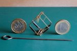
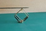
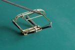
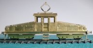
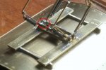
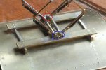
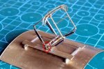
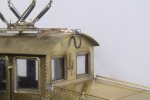
Hey presto! - an operating version.....

NER 101.jpg

Quite simply the instructions went out of the window and I turned to previous experience based on the 7mm Harton Colliery Siemens Elok (below).

Siemens 06.jpg

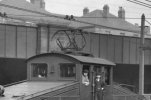
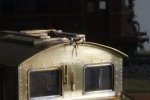
The NER ES1 pantograph (below) is not sprung in the conventional style (above) as the base is too short to include a hidden linkage to prevent the who ensemble rocking when in the raised position. It took alot of work as I cut off the dummy springs from the etch, made up upper arm end hooks from scrap etch and used four springs I had in stock.

This is a cruel crop from a photo on t'nterweb

Pantograph.jpg

NER 102.jpg

And to prove it does work...

NER 103.jpg

NER 104.jpg

NER 105.jpg

NER 106.jpg

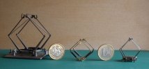
For a sense of scale here it is in between an O scale DB and a HO SBB pantograph.

NER 108.jpg

Having seen my photos, with hindsight I'm tempted to alter the upper arm spring hooks in order to extend them but as it currently works it may be best left alone. Just need to work on a locking mechansim for the lowered position. On the prototype the pantograph was raised and lowered by an insulated hand operated rod through the cab roof.
 
NER ES1

Yorkshire Dave

Western Thunderer
Further developments...

The 6 panels (2, cab ends, 2 sides and 2 bonnet/hood covers) were made up. The laminates were soldered using a blowtorch and the bonnet/hood covers were formed after annealing the half etch lines. This still resulted in a slightly multi faceted curve which I gently removed with a file. All the external details such as the handrails, vents and sand box covers were added before assembling the body.

NER 11.jpg


Before adding the sand box covers on the bonnet/hood covers I drilled out a hole to aid soldering. In addition I also drilled out the coupling socket on the internal bufferbeam to take a coupling spring.

NER 14.jpg


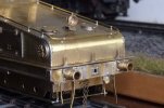
Of the additional external buffer beam detail the electric socket is a casting from Precision Scale I had in my 1/48 US parts.

NER 12.jpg


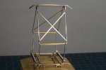
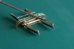
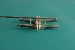
The pantograph.... The lower arm etches have teeth which if built up as non-functional are fine as they do not engage.

NER 16.jpg


However as I made mine functional I squeezed the two supports (blue) together to make the teeth (red) engage. This has greatly increased the stability of the structure and reduced the fore and aft motion of the pantograph so the head remains level whilst touching the contact wire thereby allowing for variations in the contact wire height. Later diamond pantographs have a wider base which allows for a link arm to be installed as base level to prevent the fore and aft motion and keep the structure stable.

NER 18.jpg


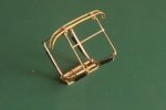
While I was tinkering with the pantograph I also added two catches (one on each side) so it can be locked down.

NER 15.jpg

NER 17.jpg

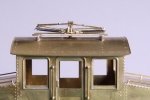
On the prototype the pantograph is raised manually by an insulated rod fixed centrally to the pantograph head and through the cab roof. It's absence is a compromise I've made (thus far) as I have made the pantograph removable with a central screw.
 
Last edited:
NER ES1

Yorkshire Dave

Western Thunderer
The last few days have seen the brake gear added to the trucks/bogies..

.....and some details not provided for in the kit.

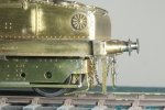
Sand pipes made up from 0.8mm brass wire fixed to the truck/bogie ends - one pair on the outer end of each truck/bogie.

NER 20.jpg


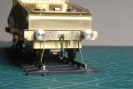
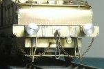
The truck/bogie swing limiting chains (and I've just spotted EMD :) on the electrical connection socket!).

NER 19.jpg


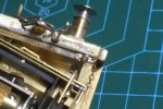
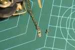
The one end of the chains are fixed to the truck frame via a bar. For the other ends I made up some small mounts from scrap etches and nickel silver wire to enable the chain to be fixed to the sill/chassis with a M1.4 screw.

NER 21.jpg

NER 22.jpg
 
NER ES1

Yorkshire Dave

Western Thunderer
A few hours at the workbench today but not much to show...

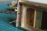
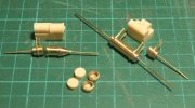
The white lumps purport to be some of the underframe casting, together with the two white buttons/dots being the headlights ..... :eek:

..... so I made up some better looking versions and more to scale from pieces of brass wire, tube and scrap brass etch..... The wires are deliberately long and will be bent and trimmed when the parts are fitted to the underframe.

NER 23.jpg

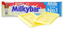
It'd been better if this was included in the kit instead.... :)

Milky Bar.jpg
Just need to look at some of the other milky bar pieces in the kit....
 
NER ES1

Yorkshire Dave

Western Thunderer
Another week, more hours at the workbench with not much to show.....:)

The fitting of Laurie Griffin lamp irons - I preferred these as they are a bit beefier and not likely to stab you (the kit supplied etch ones are thin and likely to do this!) - and my own home brewed headlamps.

NER 24.jpg


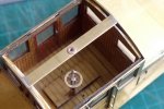
As I wanted the roof to be removable I added a brass strip across the centre line. (The brake wheel is the kit one mounted on a cut down Laurie Griffin Holden tender brake stand - after I had opened out the side holes).

NER 25.jpg

And the roof is held in by the pantograph retaining screw.

NER 26.jpg


I also built up interior walls from styrene onto which the glazing is fixed. The walls are not fixed in and self lock so I can remove them - which I'll need to do as these are incorrect for the NER loco. A new set will easily be made up.

NER 27.jpg


From scrap brass, brass wire and brass etch I made up a new switchgear board to replace the milky bar representation.

NER 28.jpg

which is held in by a countersunk M1.4 screw in the cab floor.

NER 29.jpg

Since the cab roof is removable I added spigots of 0.3mm brass wire to the roof fusebox bracket - made from scrap nickel silver etch - and the cab front.

NER 31.jpg

Onto which I can mount 0.3mm I/D silicone carp fishing rig tube to represent the electric power cable from the pantograph.

NER 32.jpg


And finally a comparison of scale with Met Bo-Bo Sir Ralph Verney.

NER 33.jpg
 

Yorkshire Dave

Western Thunderer
Thanks Rob, these are excellent. Just shows how spartan the cabs were and the reliability on common sense given the amount of exposed 600v DC electrical equipment.

I can easily make a new cab interior from styrene as the current one can be dropped out.
 

Rob Pulham

Western Thunderer
Thanks Rob, these are excellent. Just shows how spartan the cabs were and the reliability on common sense given the amount of exposed 600v DC electrical equipment.

I can easily make a new cab interior from styrene as the current one can be dropped out.
That was what struck me, just how little there actually was inside.
 
NER ES1

Yorkshire Dave

Western Thunderer
Following on from and thanks to @Rob Pulham 's ES1 cab interior photos.....

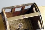
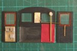
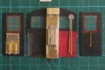
I have made up new interior cab walls and ends from styrene, and additional switch gear boxes and panels from scrap brass etch and square tube plus a pair of gauges from brass tube, a slice of clear acrylic rod and a scrap brass backing (the latter by slipping a piece of this brass in an office hole punch). The wires will be formed to shape once I have made up the air brake operating stands. The red 'curtain' is made from tissue paper.

Top left is the kit supplied cab interior detail. Bottom left is ths 'A' end and bottom right is the 'B' end details I have made.

NER 34.jpg

'B' end
NER 35.jpg

'A' end
NER 36.jpg

And a half-hearted attempt was made to try and give the bottom half of the cab ends a bit of illusional depth since the kit bulkhead is solid. :eek: :rolleyes:
 
Last edited:

Rob Pulham

Western Thunderer
Hi Dave,

Maybe too late for you now but I managed to get a few more detail photos of the ES1 on Wednesday while on a visit to the new building at Shildon. I have now organised and created a Flickr album of all my photos of ES1

ES1 on Flickr
 

Yorkshire Dave

Western Thunderer
Maybe too late for you now but I managed to get a few more detail photos of the ES1 on Wednesday while on a visit to the new building at Shildon. I have now organised and created a Flickr album of all my photos of ES1

Absolutely not too late Rob (@Rob Pulham) - the ES1 build had stalled mainly due to the underframe detail and after looking at the 'detail' parts provided in the kit again. Which has already lead me to sit and made six new fuseboxes from scrap brass.

I've had a quick look at your ES1 album and can already see it will provide more useful information regarding the underframe: namely the pipework and how the sixth fusebox and other parts are mounted. Your additional photos also confirms the cab interior layout I had deduced from various sources (including those posted by yourself earlier). They also provide sufficient information to enable me to scratchbuild the cab air brake operating stands

In hindight I wish I had elected to build ES2/2/6481/26501 as more photos exist of both sides of this one rather than ES1/1/6480/26500 which appears to have been photographed from one side only.

The other thing I found out after studying various photos is the LNER standard buffers were fitted by BR not LNER as alluded to in publications since some 1946-8 photos show both ES1 and ES2 with NER buffers. Apart from a few other subtle differences between ES1 and ES2 introduced by British Rail despite both being the same class of loco. When you come to build yours there a few things to watch out for....:eek:

I'll be a regular visitor to your ES1 Flickr album :) and if acceptable I may download some of your photos - for my use - to continue the build.
 
Back to school

Yorkshire Dave

Western Thunderer
For some unknown reason I have recently been struggling to get a 6 coupled chassis to run smoothly without binding.....

..... and it was a case of going back to basics so I aquired one of the Coinnessuer Models starter kits - namely the 0-4-0T industrial tank loco based loosely on the LSWR C14 and the Tri-ang Nellie (or Polly or Connie).

The chassis was built up broadly as per the instructions and my deviations were the fitting of roller bearings (ball race) and using SDMP/Finney7 Power gearbox to keep the motor low within the chassis. This also allows the body to be dedicated to DCC stuff - decoder, sound chamber, stay alive, etc.

Torheit 01.jpg

Torheit 02.jpg

At the end I had a sweetly running chassis with no binding.... a mega result for me. :)

Then my attention turned to the body and I spent a lot of time contemplating this as I did not want a dumpy british looking loco as if it had squashed itself by hitting the buffers....

After much bodgery (mainly altering the cab) I've ended up with this pseudo Teutonic-Dutch euro-lok....

Torheit 03.jpg

Torheit 04.jpg

Torheit 05.jpg

I've used slightly smaller wheels which did mean moving the brake gear and added additional and adapted detail parts I had kicking around in my bits box. And yes - one buffer face on each end has been flattened.

Now painted Karminrot RAL 3000 (DB undeframe red) and Ferngrün RAL 6025 which is a close match for the green used on werklok. The frames under the smokebox are deliberately devoid of detail as I plan to install Walschaerts/Heusinger valve gear at some stage. The DCC stuff will be installed in due course as will be working head and tail lights.
Torheit 06.jpg

At the end of the day I feels it's been a worthwhile exercise and provides a small fun non-serious 'neverwozzer' to mess about with. :rolleyes:

..... and for some fun....

Torheit 07.jpg

Torheit 09.jpg
 

Yorkshire Dave

Western Thunderer
I acquired this Dapol 7mm wagon to repaint and re-letter into something suitable for the Metropolitan Railway.

Tims 001.jpg

However, it turns out to be the wrong wagon for this particular coal merchant as it should be an outside braced RCH Gloucester Wagon as below (source: t'interweb, copyright: unknown). Anyway, I used it as an experiment to try my hand at lettering.

J Tims 002.jpg

To me, it appears items today are designed and built by 'Jonny half-a-jobs', and we spend so much time correcting errors and omissions. If you're going to manufacture a half decent wagon at least include the interior detail. I also understand some of it is to do with releasing items from moulds.

Here they have included the interior door bracing but as modelled the side drop doors would not open!

J Tims 02.jpg

As a result I trimmed the moulded bracing and added the reminder of the internal bracing from styrene strip. Lines were also scored to represent the door and the original lettering removed.

J Tims 06.jpg

Continuing with the lettering I found a suitable image from which I could scale and create my own stencil templates as decals are not available for this coal merchant.

J Tims 03.jpg

These were attached to the patch painted wagon body and then sprayed with a pale grey to create ghost lettering which I could tidy up.

J Tims 04.jpg

And after tidying up (sort of) with acrylics - the end result which is not brilliant by any standards but a good starting/learning point. It has a ficticious number as I don't know whether this coal merchant had any of this particular type of wagon.

J Tims 05.jpg

I'll be repeating this at some point with the correct RCH vehicle - using a Slaters RCH 7 plank wagon kit as the starting point. At least I'll be able to letter the wagon sides before assembly.

During some family history research my great, great grandmother was the ladies room attendant at Willesden Green station on the Met in the early 1900s. Her husband's early demise was a railway related accident and my deduction is the Met provided her with employment as part compensation as she had three small children at the time - one being my grandmother.
 
Top