7mm Mickoo's Commercial Workbench

7mmMick

Western Thunderer
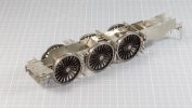
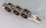
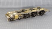
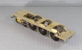
Finally completed the David Andrews A1, well almost, as is my want I do the back head as a mini (sanity break) project whilst the main engine is away for paint. The coupling and connecting rod oil pots also get added once all the motion is stripped back down.

Constant cleaning with soaps/cleaners and has tarnished the brass quicker than normal such that it's pointless trying to keep it bright past a certain point. The nickel silver chassis on the other hand is still as bright as the day it was completed many weeks ago.

Next stop is a complete strip down followed by the US cleaner then bagged up for the ride up north to the painter.

View attachment 159505

View attachment 159506

View attachment 159507

View attachment 159508
Lovely work Mick, I do like the A1’s over most of the other LNER Pacific’s
 

mickoo

Western Thunderer
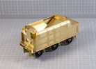
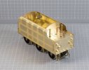
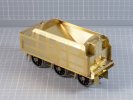
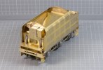
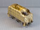
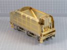
New week, new project, another David Andrews kit, this time a rebuilt Royal Scot :thumbs:

There are a few niggles, most easily overcome and I'm sure there will be more along the way, but so far nothing too drastic. I already know the fire iron tunnel rear section doesn't fit by a country mile and the coal hopper etch needed some hacking to get it to fit.

In all fairness it's not too bad and not one that'll need a full load of coal to cover up the gaps.

The white metal scoop done and water filler hatch are just hopeless and straight in the bin, 3D parts to follow in due course.

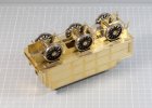
The sides are just tacked on and still require the footplate joint seam soldered and cleaned up, the internal design precludes internal soldering; so it'll be a big fat very hot iron along the outside and lots of elbow grease to clean the joint up afterward.

IMG_10957.jpg

IMG_10958.jpg

IMG_10960.jpg

IMG_10962.jpg
 

mickoo

Western Thunderer
Mick,

Have you thought about using a gas torch to run a fillet around the base of the tender sides ?

Ian
I have but there are a few factors against that, one is the material thickness, to get enough heat in the joint you end up heating the surrounding area too much due to it's thickness, the joint just soaks up the heat, burns off the flux and the solder doesn't run well. The second factor is the design, the side sheets have tabs that fit into slots in the footplate, a quite normal situation.

The problem here is that the slots are too big, so the solder will not bridge the gap just by gravity or heat alone, it needs to be dragged across by the tip of an iron.

In the end I'll whizz a bead around with the iron and then if necessary warm it with the torch to flatten any lumps and bumps out then just clean with a fiber brush. I may even just add the cosmetic filler (the sides are already firmly secured with 145°) bead in 70° gap filling solder, that runs much better and would probably flow over the gaps in the slots easier.
 

Paul Tomlinson

Western Thunderer
Mick, Are the sides half-etched to form the beading and rivet detail? There are no marks on the reverse side, suggesting that, or a double-skinned design. Have you ever built the Ragstone version (ex-MMP I believe) to compare their respective merits? Cheers, Paul.
 

mickoo

Western Thunderer
Paul,

The sides are indeed half etched...from 0.7 mm brass :eek:, twice as thick as you really need to be honest.

The beading is a flat section as part of the etch and quite chunky, but taking it off and replacing for correct half round/D profile is a non starter, you'd do to much damage to the rest of the sheet to merit the improvement.

Personally I would have gone with a 0.4 mm nickel silver side sheet with half etched rivets on it and then add the beading afterward, or, the other alternative would be a 0.3 mm brass full sheet with half etch indents on the inside to punch out the rivets and add the beading afterward.

I've not had a Ragstone or MMP engine across the bench, that's the problem with commission work, you only tend to build what you're presented with.

The DA tender isn't bad, there are worse, there are better and on average 90% of the kits go together reasonably well, which is frustrating when the last 10% doesn't.
 

Paul Tomlinson

Western Thunderer
Paul,

The sides are indeed half etched...from 0.7 mm brass :eek:, twice as thick as you really need to be honest.

The beading is a flat section as part of the etch and quite chunky, but taking it off and replacing for correct half round/D profile is a non starter, you'd do to much damage to the rest of the sheet to merit the improvement.

Personally I would have gone with a 0.4 mm nickel silver side sheet with half etched rivets on it and then add the beading afterward, or, the other alternative would be a 0.3 mm brass full sheet with half etch indents on the inside to punch out the rivets and add the beading afterward.

I've not had a Ragstone or MMP engine across the bench, that's the problem with commission work, you only tend to build what you're presented with.

The DA tender isn't bad, there are worse, there are better and on average 90% of the kits go together reasonably well, which is frustrating when the last 10% doesn't.
Mick, Thanks very much for the info. - looking forward to following your build.
 

Focalplane

Western Thunderer
Mick

I doubt if you would remember but when I built the Finney7 Princess Coronation tender a few years ago I attached the half round/D section profile "all wrong". I now realize it was having previously built a DA Fowler tender that set me off in the wrong direction. Now the Royal Scot tender shows another way of applying the beading! Would it be possible to at least carefully shave off rounded corners on the beading on the Scot tender?

Lovely work as usual! Paul
 

mickoo

Western Thunderer
Mick

I doubt if you would remember but when I built the Finney7 Princess Coronation tender a few years ago I attached the half round/D section profile "all wrong". I now realize it was having previously built a DA Fowler tender that set me off in the wrong direction. Now the Royal Scot tender shows another way of applying the beading! Would it be possible to at least carefully shave off rounded corners on the beading on the Scot tender?

Lovely work as usual! Paul
To be honest, the amount of effort involved in doing that would probably come close to all new sides, you can do the outer edge but the edge facing the skin and rivets would be a bind and quiet difficult if not near impossible around the curves at the front.

I'm of the mind to leave it all alone, even though it's wrong, rather than hack it and it looks 30% right and uneven. If you're going to work on it or change it, then do it properly with new and better bits. Don't try and waste your time hacking what's there because at the end of the day....that's exactly what it will look like, a hack.
 

Stuart Dodd

New Member
Paul,

The sides are indeed half etched...from 0.7 mm brass :eek:, twice as thick as you really need to be honest.

The beading is a flat section as part of the etch and quite chunky, but taking it off and replacing for correct half round/D profile is a non starter, you'd do to much damage to the rest of the sheet to merit the improvement.

Personally I would have gone with a 0.4 mm nickel silver side sheet with half etched rivets on it and then add the beading afterward, or, the other alternative would be a 0.3 mm brass full sheet with half etch indents on the inside to punch out the rivets and add the beading afterward.

I've not had a Ragstone or MMP engine across the bench, that's the problem with commission work, you only tend to build what you're presented with.

The DA tender isn't bad, there are worse, there are better and on average 90% of the kits go together reasonably well, which is frustrating when the last 10% doesn't.
I have built 3 of these David Andrews stanier tenders, 2 riveted and 1 part riveted, always found the beading a disappointment but there is difficulty to improve this without incurring much work.
Your build looks superb!
 

mickoo

Western Thunderer
I have built 3 of these David Andrews stanier tenders, 2 riveted and 1 part riveted, always found the beading a disappointment but there is difficulty to improve this without incurring much work.
Your build looks superb!
You're right, but to be fair if all the beading is the same then the whole is greater than the parts.

I read somewhere from one of the modelling greats, that a model at 100% quality with one part at 80% will look worse than a whole model at 75%. The art is to make the eye flow and not jar at either really good, or really bad parts.
 
Do you look down the chimney on the real ones? What about the lack of smoke and steam on the model or are we going to start selling that with the Invisible Solder. There I was thinking you were Sensible Mick to Mad Viking Mick! :)):p:)):p:)):p:))
Only just read this question re the BLP smokebox chamber and I can answer in the affirmative, Mi Lud. As a callow youth spotting in South Devon, I'd occasionally take a trip up to Exeter to sample the other railway at Saint Davids. This eventually led to trips up the bank always in the rear coach with head hanging out to sample the cacophany from one or even two 'Zs' shoving hard at the back.

At the Waterloo end of Central Station there was an exit onto New North Road from where the big and smaller Bullied pacifics could be seen starting off up the bank towards Exmouth Junction. The exhaust was so soft that I could indeed look straight down the chimney but I can't recall ever seeing all that lovely detail around the blast pipe!
 
Last edited:

mickoo

Western Thunderer
DA Royal Scot tender all done, well not quite :cool:

The fire iron tunnel was/is a dogs dinner, the angles, bends and shape are never going to work, it takes a lot of hacking to get it to fit in the available space and then to find it's all to short by a couple of mm, pahh. Anyway a quick discussion with the client and it'll either go in as it is with full coal, or if half empty then I'll add a fillet to the rear and blend it all in, as such it's only held in with sticktion for the photos. This of course means that the coal space water tank vents are not yet fitted either.

The 3D dome and filler are also loose fitted, they'll be secured once the whole lot has been through the US cleaner as I've noticed some small pock marking on previous prints after they've been through the cleaner.

Overall it's not that a bad kit to make, you do have to think ahead and change the order of certain parts, for example, add the rear grab rail and front hand rail knobs before you fit the side, especially the lower hand rail knob as it's totally inaccessible to solder from the inside once the side is fitted.

You might be able to get away with the lower hand rail knob if the lower cab floor section isn't fitted but you really need that in place to get an accurate turn in on the sides.

Other bits best fitted early are the handbrake and water scoop handle plates to the front lower bulkhead and the water gauge by the locker, both of which I didn't do but managed to sneak some solder in to secure them.

I also fitted the rivet strip around the rear deck and lifting lugs before the sides went on, all the soldering being on the edge of the deck or from the inside.

IMG_10967.jpg

IMG_10964.jpg

IMG_10966.jpg
 

mickoo

Western Thunderer
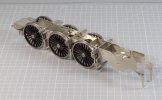
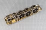
Bimbling along the DA Royal Scot chassis is up and running, nothing too untoward, a couple of stay tabs in the wrong place, or the slots, either way they didn't fit. I just filled the edge of the offending tabs until the stay fitted. The worst is the mid frame L shaped one, it ended up sticking out below the frames by about 2 mm.

The springs were a triple laminate combined with J hangers and keep plate, no good if you want to add sprung axle boxes, in addition the rear and intermediate were joined with some sort of ash pan representation. I cut the J hangers off and kept them, new 3D springs, keeps and guides will be fitted later. The springs will be held in place at the bottom with pins and securing nuts below the snubbing blocks. I'll also need to fabricate a new ash pan once the motor and mount are in place.

IMG_0991.jpg

IMG_0992.jpg

IMG_0994.jpg
 

mickoo

Western Thunderer
A little more progress on the DA Royal Scot.

Watch your bogie pivot, it's in the wrong place, well, it might actually be right and everything else is wrong Consequently the rear bogie wheel smacks the brake gear and is not quite centered in the frame arches.

The root of the problem is the L shaped stay with the securing nut, the vertical part of the stay/slot/tab is too far back by just over 1 mm so you have to trim the horizontal tabs to fit into the horizontal slot in the frames behind the cylinders. You only find this out much later when you've made the bogie and brake gear.

The solution is simple, remove the bogie pivot nut, open the hole out toward the front and re affix the nut. It's a bit more convoluted as the nut sits in an etched recess, thus when you move it forward half is on full thickness material and half on a half etch material; it's very easy for the nut to tilt when re-affixing and the bogie pivot post becomes out of line.

Having done that there is plenty of clearance behind the rear bogie wheel and frame arches.

The piston stuffing gland/slide bar casting is....well...very good, just a waft of a file to clean up and the fit is perfect in the etched slide bar bracket, same for the valve and slide block casting.

IMG_10999.jpg

IMG_11000.jpg

IMG_11001.jpg
 

Lancastrian

Western Thunderer
Mick,

As you're doing replacement springs, are you working from the etches or works drawings ? Don't forget to allow for compression of the loco sitting on them :thumbs:

Ian
 

mickoo

Western Thunderer
Mick,

As you're doing replacement springs, are you working from the etches or works drawings ? Don't forget to allow for compression of the loco sitting on them :thumbs:

Ian
Well now, there's a point worth expanding on.

First off drawings will be the source information, I have very little faith in anything on this DA, or any DA kit, being 100% accurate. That's not a hidden criticism but an observation from building the kits; possibly because when the kits were drawn out the information wasn't available at the time (NRM library).

Second, depicting weighted engines on springs, some points to consider.

If you hadn't have mentioned it, would anyone know the difference.
You have mentioned it and I don't bother, would anyone notice the difference.
If I do add it, do I now to go back and alter all the tender axles boxes/springs to suit whatever coal load I put in, typically most kit tender springs are near empty.
If I do add them, should I then replace the kits passing nod to the J hanger profile to suit the more accurate springs with weight compensation.
If I make new J hangers should I then upgrade all the brake hangers, pivots and shoes.
If I make new brake gear should I then make all new accurate frame spacers.
If I make all new frame spacers should I now make new plate frames to the correct profile.

Where do you stop :D

On a green field site you can tailor everything to match, the DA kits are brown field sites and you're always going to be dragged back by the lowest denominator, therefore is there any real point adding bits that are 100% accurate when the rest of the model is barely 80% accurate?

For the record the springs will be weight compensated, simply because it takes no extra effort at all to draw the curved lines at a shallower radius. I have no idea what that radius will be, the drawings show an empty engine and I have no clue how much Royal Scot driving wheels deflect when fully loaded. In short I'm going to 'best guess' which then begs the question, if I don't know does anyone else and will they be able to tell the difference ;)
 

OzzyO

Western Thunderer
Hello Mick,

if the buffer height is showing the normal height for them just leave as is on the drawing, I would not expect the deflection of the springs to be much more than about 1/8" if that.

OzzyO.
 
Top