You are using an out of date browser. It may not display this or other websites correctly.
You should upgrade or use an alternative browser.
You should upgrade or use an alternative browser.
An Occasional Series: By Jonte
- Thread starter jonte
- Start date

jonte
Western Thunderer
I did indeed notice the little ‘issues’ you’ve been experiencing with the build, Jan.
It sometimes begs the question I shaln’t mention
My wife often asks why I put myself through it, and perhaps I often ask the same of myself, as I’m quite sure you do too at times, Jan. Perhaps it’s all some sort of Purgatory")
I was considering ordering a new kit and starting afresh to be honest, Jan, but then I would much rather prefer to be working in brass, as soldered construction can be more forgiving in terms of adjustments, at least more so than solvent. And of course, they don’t come cheap so there would be the added expense to consider; additionally, my mechanism kit is designed solely for the Peco kit so that would have been a waste too, which makes any replacement a Hobson’s choice
Never mind; onwards and upwards. At least I can battle on without the worry of damaging the base now. Every cloud hey, Jan?")
It sometimes begs the question I shaln’t mention
My wife often asks why I put myself through it, and perhaps I often ask the same of myself, as I’m quite sure you do too at times, Jan. Perhaps it’s all some sort of Purgatory
I was considering ordering a new kit and starting afresh to be honest, Jan, but then I would much rather prefer to be working in brass, as soldered construction can be more forgiving in terms of adjustments, at least more so than solvent. And of course, they don’t come cheap so there would be the added expense to consider; additionally, my mechanism kit is designed solely for the Peco kit so that would have been a waste too, which makes any replacement a Hobson’s choice
Never mind; onwards and upwards. At least I can battle on without the worry of damaging the base now. Every cloud hey, Jan?
jonte
Western Thunderer
The briefest of updates.
Following the reinforcement of the outside of the well wall with 1.5mm thick styrene as outlined in my last, today’s aim was to remove anything up to 1.5 mm of wall from the inside, in order to allow add relief (as shown) that wouldn’t cause the bridge to bind. Unfortunately, the kit is not a perfect circle and increases in arc towards the three points were the sections are joined.
So this is where I decided to make a start.
I employed this trumped up implement your gauge a consistent removal of material:

Unfortunately, it was as much use as a chocolate teapot, so it was decided to remove the maximum material from the points described, with a token amount from elsewhere.
However, the drum-like shape of the well amplified the screams of the Dremel, breaching the peace of this quiet neighbourhood in the process. To be frank, all it did was melt the residue into sharp lumps of plastic which obstructed the path of the noisy implement. Accepting I was beaten, I withdrew to consider my options.
A couple of cups of tea later, and dissatisfied with the solutions open to me, I decided to see if the well could be rescued. The rescue attempt consisted merely of my taking a chisel shaped blade to the plastic blobs still firmly attached, and the cutting of thin strips (0.3mm) of styrene sheet with which to try and conceal the creator like wall:

The 1.5mm styrene sheet employed to reinforce the outside of the wall can be seen, needless as it proved to be.
A quick test with the bridge temporarily attached revealed unobstructed running,however, even using my thinnest section styrene, there simply wasn’t enough room to add the detail I desired without gumming up the works again.
It really was a pointless exercise, and one hard learned.
Despite the less than perfect surface that once adorned the kit, I think that some ‘dressing’ using stored photos of concrete wells as a guide, should hide a multitude of sins, albeit not the ‘look’ intended.
It’s all a bit disappointing really, but one can only work with what they’ve got; when all’s said and done, the priority is that it works.
At least there’s isn’t the burden of extra cost, apart from the purchase of some extra styrene sheet.
Jonte
Following the reinforcement of the outside of the well wall with 1.5mm thick styrene as outlined in my last, today’s aim was to remove anything up to 1.5 mm of wall from the inside, in order to allow add relief (as shown) that wouldn’t cause the bridge to bind. Unfortunately, the kit is not a perfect circle and increases in arc towards the three points were the sections are joined.
So this is where I decided to make a start.
I employed this trumped up implement your gauge a consistent removal of material:
Unfortunately, it was as much use as a chocolate teapot, so it was decided to remove the maximum material from the points described, with a token amount from elsewhere.
However, the drum-like shape of the well amplified the screams of the Dremel, breaching the peace of this quiet neighbourhood in the process. To be frank, all it did was melt the residue into sharp lumps of plastic which obstructed the path of the noisy implement. Accepting I was beaten, I withdrew to consider my options.
A couple of cups of tea later, and dissatisfied with the solutions open to me, I decided to see if the well could be rescued. The rescue attempt consisted merely of my taking a chisel shaped blade to the plastic blobs still firmly attached, and the cutting of thin strips (0.3mm) of styrene sheet with which to try and conceal the creator like wall:
The 1.5mm styrene sheet employed to reinforce the outside of the wall can be seen, needless as it proved to be.
A quick test with the bridge temporarily attached revealed unobstructed running,however, even using my thinnest section styrene, there simply wasn’t enough room to add the detail I desired without gumming up the works again.
It really was a pointless exercise, and one hard learned.
Despite the less than perfect surface that once adorned the kit, I think that some ‘dressing’ using stored photos of concrete wells as a guide, should hide a multitude of sins, albeit not the ‘look’ intended.
It’s all a bit disappointing really, but one can only work with what they’ve got; when all’s said and done, the priority is that it works.
At least there’s isn’t the burden of extra cost, apart from the purchase of some extra styrene sheet.
Jonte
Stephen Freeman
Western Thunderer
Personally I think it is easier to cut the well from layers of MDF with a router, though there are times where the size required defeats my router and then it's back to a hole cutter which isn't as easy but for scales below 4mm usually necessary.
jonte
Western Thunderer
Btw: one of the options mentioned in my last post, Stephen, was a visit to your website.Personally I think it is easier to cut the well from layers of MDF with a router, though there are times where the size required defeats my router and then it's back to a hole cutter which isn't as easy but for scales below 4mm usually necessary.
They do indeed look the bees knees, but as there was no price list, I considered it a case of ‘if you have to ask….’
Properly engineered, with a lifetime of good service, they’re probably the benchmark for turntables, but no doubt well out of my price range.
Jonte
jonte
Western Thunderer
The pace of work has slowed for several reasons of late, not least of all due to the need for further cogitation.
Unfortunately, a chicken & egg situation has occurred with the turntable build, as I’ve been conjuring up ways - some viable - to reduce the amount of ‘decorating’ required after the fitting of the bridge and its workings.
You may recall that the design of the kit prevented much relief being added to the walls to necessitate the unobstructed turning of the bridge, however, I still wanted to show some detail around the top edge as can be seen in the previous photo I’m working from, and which I’ll reproduce to save you wading through several previous posts:

In particular, it’s the iron shuttering (replete with drainage holes) and the adjacent fatigued render I’d like to represent. I’ve worked out a ‘frame’ method for supporting this detail, as much of it is in the form of plaster (gypsum), which is fabricated from lengths of styrene section and strips of embossed brick, a great surface for the plaster to adhere to. However, this requires knowledge of where the roads will be sited; hence the ponderings and their frustrating obstacle to progress. I won’t bore you with the full details, but to compound matters, there’s the instructions that accompany the Locomotech indexing system to take into account, which consists of a slim brass disc which has five slits cut into it to represent each of the maximum five roads allowed. Apparently, they ‘default’ to the Setrack settings commensurate with the template included in the Peco kit, although - much like the idea I had with the Arduino system I mooted at the beginning of the thread, controls are offered to assist with customised roads around the edge.
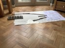
To cut a long story short, I decided it was about time to draw out the Peco plan for myself to see if this would help (it did, sort of, but not completely), and also to see how the dimensions of the plan would be affected, bearing in mind I’ve deviated from the plan’s Setrack based idea. To that end, I cut up an old roll of wallpaper to size, to which I stuck the Peco template, reckoning that it would be best to develop the layout from the location of the turntable:


 In the end, it proved its weight in gold: I have a better idea of where the entry road will go and the exit roads to aid decoration/detailing of the edge, and I’ve discovered that a further six inches in length will be required to accommodate the Peco Loco lift, and allow a longer run for the shed roads.
Elsewhere, I reassessed my inclusion of an inspection ‘tunnel’. Whilst I haven’t abandoned the idea altogether, I decided to do so in half relief, following assimilation of the accompanying Locomotech notes, which mentions using the centre slot of the five for the entry road, in effect a form of datum from which to gauge the exit roads. Essentially, it advises loosening off the motor coupling to do so, which raised thoughts of perhaps making some adjustments of the siting of the well in the hole, with me thinking it would be darned sight easier if the well could be kept circular, hence the half relief option for the tunnel. Here’s one I took earlier during the recent clement spell, although further detailing has since been added:

You might just notice the ‘frame system’ I’ve adopted, about which I made mention further up.
I’ve also prepared a set of wooden rails/beads for attaching to the sides of the deck, as per the one in the photos further back of Leeds Central:

Tacked on with blutac for now, there are six in total (three per side), onto which I’ve included a worn paint effect using Tamiya flat white (even though it looks blue!). This was copied from the photo of that of Leeds, although it could have been a reflection of the light. Still, it looked interesting and broke up the dirty wood effect of the deck.
So, I’ll carry on with renewed vigour now I have a better idea of where the detailing will go, although I’m pretty certain I won’t manage it all before I have to wire it up.
Thanks for looking.
Jonte
Unfortunately, a chicken & egg situation has occurred with the turntable build, as I’ve been conjuring up ways - some viable - to reduce the amount of ‘decorating’ required after the fitting of the bridge and its workings.
You may recall that the design of the kit prevented much relief being added to the walls to necessitate the unobstructed turning of the bridge, however, I still wanted to show some detail around the top edge as can be seen in the previous photo I’m working from, and which I’ll reproduce to save you wading through several previous posts:
In particular, it’s the iron shuttering (replete with drainage holes) and the adjacent fatigued render I’d like to represent. I’ve worked out a ‘frame’ method for supporting this detail, as much of it is in the form of plaster (gypsum), which is fabricated from lengths of styrene section and strips of embossed brick, a great surface for the plaster to adhere to. However, this requires knowledge of where the roads will be sited; hence the ponderings and their frustrating obstacle to progress. I won’t bore you with the full details, but to compound matters, there’s the instructions that accompany the Locomotech indexing system to take into account, which consists of a slim brass disc which has five slits cut into it to represent each of the maximum five roads allowed. Apparently, they ‘default’ to the Setrack settings commensurate with the template included in the Peco kit, although - much like the idea I had with the Arduino system I mooted at the beginning of the thread, controls are offered to assist with customised roads around the edge.
To cut a long story short, I decided it was about time to draw out the Peco plan for myself to see if this would help (it did, sort of, but not completely), and also to see how the dimensions of the plan would be affected, bearing in mind I’ve deviated from the plan’s Setrack based idea. To that end, I cut up an old roll of wallpaper to size, to which I stuck the Peco template, reckoning that it would be best to develop the layout from the location of the turntable:
In the end, it proved its weight in gold: I have a better idea of where the entry road will go and the exit roads to aid decoration/detailing of the edge, and I’ve discovered that a further six inches in length will be required to accommodate the Peco Loco lift, and allow a longer run for the shed roads.Elsewhere, I reassessed my inclusion of an inspection ‘tunnel’. Whilst I haven’t abandoned the idea altogether, I decided to do so in half relief, following assimilation of the accompanying Locomotech notes, which mentions using the centre slot of the five for the entry road, in effect a form of datum from which to gauge the exit roads. Essentially, it advises loosening off the motor coupling to do so, which raised thoughts of perhaps making some adjustments of the siting of the well in the hole, with me thinking it would be darned sight easier if the well could be kept circular, hence the half relief option for the tunnel. Here’s one I took earlier during the recent clement spell, although further detailing has since been added:
You might just notice the ‘frame system’ I’ve adopted, about which I made mention further up.
I’ve also prepared a set of wooden rails/beads for attaching to the sides of the deck, as per the one in the photos further back of Leeds Central:
Tacked on with blutac for now, there are six in total (three per side), onto which I’ve included a worn paint effect using Tamiya flat white (even though it looks blue!). This was copied from the photo of that of Leeds, although it could have been a reflection of the light. Still, it looked interesting and broke up the dirty wood effect of the deck.
So, I’ll carry on with renewed vigour now I have a better idea of where the detailing will go, although I’m pretty certain I won’t manage it all before I have to wire it up.
Thanks for looking.
Jonte
Attachments
jonte
Western Thunderer
Time has been at a premium of late, thus progress has been glacial.
In fact, it seems even longer without activity than the three weeks or so that’s elapsed since I completed the framework to support the top edge of the well as per this shot of the real thing, which I’ve posted before merely for reference, and do so again trusting nobody minds:

And the framework:

The gaps (four in total) are where the roads to and from the turntable will be situated. They’re arbitrary for now, although the template provided by Peco was superimposed on my full size track plan to ensure a little more accuracy. No further work can be undertaken here until the motor is attached and precise locations determined.
Incidentally, the height of the top edge has been calculated to sit just below the head of the rails of the tracks, this to allow track cleaning without removing the paint from the edge. In real life, of course, this was level with the top of the rails, but like the oversized flangeways, it’s all for purpose of expediency.
During the occasional (please forgive the pun) visit, I’ve begun to build up some texture to the walls, testing all the time with the bridge in place, due to the tight tolerances mentioned previously:


Work will continue on the walls until I’ve covered it, hopefully the end product being something reminiscent of the previous prototype shot. A few more days work in that respect should see it completed and primed like the base.
Meanwhile, I’ve revisited the ‘wooden’ bridge rails which have received further distressing with oils and enamel washes. Earlier, I managed to fix them in place at long last:


I’m trusting that the ones attached to that of the turntable at Leeds Central station shown several posts back, also sported chipped white paint with the presence of some streaking. Perhaps it’s just a trick of the light on the photograph? Anyway, it’s there on the model; hopefully to bring some relief to all that dirty timber above it.
So that’s it for now.
Thanks for looking.
jonte
In fact, it seems even longer without activity than the three weeks or so that’s elapsed since I completed the framework to support the top edge of the well as per this shot of the real thing, which I’ve posted before merely for reference, and do so again trusting nobody minds:
And the framework:
The gaps (four in total) are where the roads to and from the turntable will be situated. They’re arbitrary for now, although the template provided by Peco was superimposed on my full size track plan to ensure a little more accuracy. No further work can be undertaken here until the motor is attached and precise locations determined.
Incidentally, the height of the top edge has been calculated to sit just below the head of the rails of the tracks, this to allow track cleaning without removing the paint from the edge. In real life, of course, this was level with the top of the rails, but like the oversized flangeways, it’s all for purpose of expediency.
During the occasional (please forgive the pun) visit, I’ve begun to build up some texture to the walls, testing all the time with the bridge in place, due to the tight tolerances mentioned previously:
Work will continue on the walls until I’ve covered it, hopefully the end product being something reminiscent of the previous prototype shot. A few more days work in that respect should see it completed and primed like the base.
Meanwhile, I’ve revisited the ‘wooden’ bridge rails which have received further distressing with oils and enamel washes. Earlier, I managed to fix them in place at long last:
I’m trusting that the ones attached to that of the turntable at Leeds Central station shown several posts back, also sported chipped white paint with the presence of some streaking. Perhaps it’s just a trick of the light on the photograph? Anyway, it’s there on the model; hopefully to bring some relief to all that dirty timber above it.
So that’s it for now.
Thanks for looking.
jonte
Lyndhurstman
Western Thunderer
Lovely modelling as ever, @jonte. Both the table and the well are looking great.Time has been at a premium of late, thus progress has been glacial.
In fact, it seems even longer without activity than the three weeks or so that’s elapsed since I completed the framework to support the top edge of the well as per this shot of the real thing, which I’ve posted before merely for reference, and do so again trusting nobody minds:
View attachment 166639
And the framework:
View attachment 166633
The gaps (four in total) are where the roads to and from the turntable will be situated. They’re arbitrary for now, although the template provided by Peco was superimposed on my full size track plan to ensure a little more accuracy. No further work can be undertaken here until the motor is attached and precise locations determined.
Incidentally, the height of the top edge has been calculated to sit just below the head of the rails of the tracks, this to allow track cleaning without removing the paint from the edge. In real life, of course, this was level with the top of the rails, but like the oversized flangeways, it’s all for purpose of expediency.
During the occasional (please forgive the pun) visit, I’ve begun to build up some texture to the walls, testing all the time with the bridge in place, due to the tight tolerances mentioned previously:
View attachment 166632View attachment 166634View attachment 166635
Work will continue on the walls until I’ve covered it, hopefully the end product being something reminiscent of the previous prototype shot. A few more days work in that respect should see it completed and primed like the base.
Meanwhile, I’ve revisited the ‘wooden’ bridge rails which have received further distressing with oils and enamel washes. Earlier, I managed to fix them in place at long last:
View attachment 166636View attachment 166637View attachment 166638
I’m trusting that the ones attached to that of the turntable at Leeds Central station shown several posts back, also sported chipped white paint with the presence of some streaking. Perhaps it’s just a trick of the light on the photograph? Anyway, it’s there on the model; hopefully to bring some relief to all that dirty timber above it.
So that’s it for now.
Thanks for looking.
jonte
Cheers
Jan
jonte
Western Thunderer
Most kind, Jan; thank you
I’d intended to leave the walls flat as you may remember following the disaster with the thinned embossed brick exercise, trusting to paint to suggest texture.
However, as the dish isn’t perfectly circular, there’s greater allowance for error in places, hence the testing with the plaster, which is easier to adjust or remove than plastic
What you see is probably the max I can get away with all round, so I can use this to gauge any additional work by. While it looks quite substantial on camera, in reality it’s pretty much wafer thin, and should help to convey some of the relief of the subject in the first picture.
Your interest, Jan, is as always very much appreciated.
Thanks again, chum
Jonte
jonte
Western Thunderer
Pleased to report that work is almost complete on the well wall, apart from some minor detailing around the rails area, so I’d just like to post some photos to show progress.
First, the prototype I’ve been using as a guide to remind you:

I did a little digging, and at long last I’m able to attribute and give credit to the photographer: M.Mensing. I’ve also established it”s an image of the roundhouse at Saltley engine shed.
The model:


Still in the raw so to speak and in need of a good clean to remove the dust that’s also clogging some of the detail.
Talking of which, sadly I cannot - even if able - replicate in full that of the original, as any additional relief clogs up the works and the dreaded bridge starts to bind again. In fact, what you see is tantalisingly wafer thin, and despite an urge to continue adding, I’m all too aware that to do so would compromise smooth running, so it will have to do, I’m afraid.
The next two shots show the framing being added around the entry/exit road which will hold the plaster, as I did around the edge of the dish:


Unfortunately, the generous flangeways dictated by coarser wheeled stock likely to be used, and also allowing for Hornby type couplings, dictate the diminutive sizes of the steel supports between the rails compared to those of the prototype, and like the kit itself: it is what it is.
And here’s one of the finished framing replete with plaster infilling:

As per the walls, I need to remove the dust that’s clogging some of the finer detail, and further detail around the edges.
Then it’ll be a final clean before priming and applying a dark undercoat.
Thanks for looking.
jonte
First, the prototype I’ve been using as a guide to remind you:
I did a little digging, and at long last I’m able to attribute and give credit to the photographer: M.Mensing. I’ve also established it”s an image of the roundhouse at Saltley engine shed.
The model:
Still in the raw so to speak and in need of a good clean to remove the dust that’s also clogging some of the detail.
Talking of which, sadly I cannot - even if able - replicate in full that of the original, as any additional relief clogs up the works and the dreaded bridge starts to bind again. In fact, what you see is tantalisingly wafer thin, and despite an urge to continue adding, I’m all too aware that to do so would compromise smooth running, so it will have to do, I’m afraid.
The next two shots show the framing being added around the entry/exit road which will hold the plaster, as I did around the edge of the dish:
Unfortunately, the generous flangeways dictated by coarser wheeled stock likely to be used, and also allowing for Hornby type couplings, dictate the diminutive sizes of the steel supports between the rails compared to those of the prototype, and like the kit itself: it is what it is.
And here’s one of the finished framing replete with plaster infilling:
As per the walls, I need to remove the dust that’s clogging some of the finer detail, and further detail around the edges.
Then it’ll be a final clean before priming and applying a dark undercoat.
Thanks for looking.
jonte
jonte
Western Thunderer
Getting steadily darker:


……….and darker still:


Whilst not a ‘faithful’ replica of Saltley, I hope it’s captured its flavour.
I forgot to mention in my last post that I’d done a ‘U’ turn on my decision to leave the siting of the rail positions until after the motor and disc had been attached. In reality, it would have been extremely difficult to carry out scenics of this nature with the bridge in position, thus I decided to bite the bullet and use the default positions, determined with the help of the Peco template, to carry out the necessary scenic additions without the obstacle. Whilst this is only approximate, I can use the ‘brake’ facility (potentiometer) supplied in the kit to programme the position of the rails in situ (should be accurate to within a degree or less of increment). I suppose the benefit of Code 100 is apparent here.
So there we are for now: the well, primed and undercoated ready for painting.
To save boring you all with the painting/weathering process, I’ll return when the turntable is finally ready for the fitting of the motorising kit.
Until then, thanks for looking and also to those who’ve kind enough to follow and flatter with ‘likes’.
jonte
……….and darker still:
Whilst not a ‘faithful’ replica of Saltley, I hope it’s captured its flavour.
I forgot to mention in my last post that I’d done a ‘U’ turn on my decision to leave the siting of the rail positions until after the motor and disc had been attached. In reality, it would have been extremely difficult to carry out scenics of this nature with the bridge in position, thus I decided to bite the bullet and use the default positions, determined with the help of the Peco template, to carry out the necessary scenic additions without the obstacle. Whilst this is only approximate, I can use the ‘brake’ facility (potentiometer) supplied in the kit to programme the position of the rails in situ (should be accurate to within a degree or less of increment). I suppose the benefit of Code 100 is apparent here.
So there we are for now: the well, primed and undercoated ready for painting.
To save boring you all with the painting/weathering process, I’ll return when the turntable is finally ready for the fitting of the motorising kit.
Until then, thanks for looking and also to those who’ve kind enough to follow and flatter with ‘likes’.
jonte
Attachments
Lyndhurstman
Western Thunderer
Again, some wonderful attention to detail and hue here, Jon. The colouration is evocative enough to smell! Fingers crossed that the motorising goes according to plan.Getting steadily darker:
View attachment 167804View attachment 167805View attachment 167806
……….and darker still:
View attachment 167807View attachment 167808View attachment 167809View attachment 167810
Whilst not a ‘faithful’ replica of Saltley, I hope it’s captured its flavour.
I forgot to mention in my last post that I’d done a ‘U’ turn on my decision to leave the siting of the rail positions until after the motor and disc had been attached. In reality, it would have been extremely difficult to carry out scenics of this nature with the bridge in position, thus I decided to bite the bullet and use the default positions, determined with the help of the Peco template, to carry out the necessary scenic additions without the obstacle. Whilst this is only approximate, I can use the ‘brake’ facility (potentiometer) supplied in the kit to programme the position of the rails in situ (should be accurate to within a degree or less of increment). I suppose the benefit of Code 100 is apparent here.
So there we are for now: the well, primed and undercoated ready for painting.
To save boring you all with the painting/weathering process, I’ll return when the turntable is finally ready for the fitting of the motorising kit.
Until then, thanks for looking and also to those who’ve kind enough to follow and flatter with ‘likes’.
jonte
Cheers
Jan
jonte
Western Thunderer
Sincerest thanks for your kind encouragement once more, Jan.Again, some wonderful attention to detail and hue here, Jon. The colouration is evocative enough to smell! Fingers crossed that the motorising goes according to plan.
Cheers
Jan
To be frank, while this looks okay to the naked eye, the almost ‘electron microscope resolving power’ of today’s cameras make the surface look too pitted, even though it’s no more than 0.25mm thick!
So this morning, it was back out with the masking tape and gypsum in an attempt to smooth things over
I think what swung it was due to me tracing the location in order to give credit to the photographer. In doing so, I discovered further photos which showed the render in better condition, and as the saying goes, ‘once seen…..’
My first method was probably the best, but I changed tac when it looked a little bland to the naked eye. Maybe next time….
Hopefully what results will be a halfway house

Will it ever be finished…….
And with mention of further photos, I chanced upon a colour shot of the wall, which if not of Saltley is somewhere pretty similar, of which I took a screen shot and ferreted away some time ago as you can see from the date, so once again I can’t attribute credit
Anyway, here it is to give you an idea of what I’m aiming for:

Wouldn’t it be just my luck to discover that none of it works electrically after all this………
At least I know that power is getting through to the deck rails
Many thanks once again, Jan, for your kind interest.
Jon
michael mott
Western Thunderer
Looks like you have captured the look perfectly to me Jon, this image looks as if you went back in time and took a coloured picture of the full size one.

Michael
Michael
jonte
Western Thunderer
I’m delighted, Michael, for your kind words, and perhaps I shouldn’t doubt those of modellers of your’s, and of course, my good friend Jan’s calibre.Looks like you have captured the look perfectly to me Jon, this image looks as if you went back in time and took a coloured picture of the full size one.
View attachment 167871
Michael
Let’s just say I’m rarely satisfied
Many thanks, Michael.
Jon
jonte
Western Thunderer
An interim post to report that as per usual, matters are not progressing as quickly as one would like.
The problems that have had me spending more time thinking and testing rather than doing, are two fold:
1. The base is ‘based’ on an exterior turntable from one shed; the other on an interior roundhouse from another, each sporting entirely different ‘finishes’. So how to marry? Do I extend the filth and decrepitude of that of the wall to the base, and make up the weathering thereon, or do I clean up the face, meaning that I lose the effect I’ve been striving for in that regard? In the end, I decided to keep both, the solution being to use the rail as a handy point of demarcation. With the bridge in place, I doubt there will be too much of the base to contrast, so that’s the first problem solved as I see it.
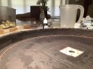
2. Returning to the base, I’ve decided in my infinite wisdom to model it in the condition shown in the following two photos and to steer away from ‘general weathering:


The problem here is that there are several shades on show, so where to start? Scrutinising, it’s apparent that there’s a dark greyish underlying shade, so that was my starting point.
The easiest solution would have been to mix up a couple of shades of grey and run with it, but I feared that it would look too flat and more than a little washed out, so I went with the usual blue/stone/sand colours mixed with a dash or two of Matt white and black enamels that contribute to an overall concrete look. While this provided all the usual hues of concrete, the contrast - and code - was a little too stark, and bore absolutely no resemblance to that in the pictures.
Consequently, I employed a series of black washes in between each of the three colour applications, finished off by two more ‘heavier’ washes, that thankfully, have toned it all down and blended each of the shades, serving hopefully to vaguely resemble those in the pictures:


As I say, these are all the usual shades of concrete; no greys have been used.
Satisfied that I now have a starting point, at last I can make a start on broaching the array of other shades which contribute to the overall look of the prototype.
Cheers for now.
jonte
The problems that have had me spending more time thinking and testing rather than doing, are two fold:
1. The base is ‘based’ on an exterior turntable from one shed; the other on an interior roundhouse from another, each sporting entirely different ‘finishes’. So how to marry? Do I extend the filth and decrepitude of that of the wall to the base, and make up the weathering thereon, or do I clean up the face, meaning that I lose the effect I’ve been striving for in that regard? In the end, I decided to keep both, the solution being to use the rail as a handy point of demarcation. With the bridge in place, I doubt there will be too much of the base to contrast, so that’s the first problem solved as I see it.
2. Returning to the base, I’ve decided in my infinite wisdom to model it in the condition shown in the following two photos and to steer away from ‘general weathering:
The problem here is that there are several shades on show, so where to start? Scrutinising, it’s apparent that there’s a dark greyish underlying shade, so that was my starting point.
The easiest solution would have been to mix up a couple of shades of grey and run with it, but I feared that it would look too flat and more than a little washed out, so I went with the usual blue/stone/sand colours mixed with a dash or two of Matt white and black enamels that contribute to an overall concrete look. While this provided all the usual hues of concrete, the contrast - and code - was a little too stark, and bore absolutely no resemblance to that in the pictures.
Consequently, I employed a series of black washes in between each of the three colour applications, finished off by two more ‘heavier’ washes, that thankfully, have toned it all down and blended each of the shades, serving hopefully to vaguely resemble those in the pictures:
As I say, these are all the usual shades of concrete; no greys have been used.
Satisfied that I now have a starting point, at last I can make a start on broaching the array of other shades which contribute to the overall look of the prototype.
Cheers for now.
jonte
jonte
Western Thunderer
I’ve reached the point where I feel I’ve travelled as far as I can with the base, and it’s well and truly time to move on to addressing the walls.
First a reminder of what it ‘should’ look like:


What I’ve ended up with:


The reason it’s taken so long is that (lame excuse time) a true likeness of the prototype just didn’t sit right. In fact, all it needed was a luminous green and bright yellow lichen adorning the edges, and it would have looked for all the world like a straight lift from a Triang/Hornby catalogue circa 1971, so vivid were the colours, to say nothing of the stark contrast, especially the yellow-ey coloured concrete.
So what followed was a paint and repaint in many areas just to tone down the whole ensemble, in order to make it a little more presentable IMHO. This was followed by a litany of washes and dry brushing just to try and blend the composition, to say nothing of subduing the effect.
I’m not sure now, whether it was a bum decision afterall to employ the rectangular sections, which are more akin to a Second World War aerodrome than a railway turntable, but it was crying out for a little more interest, and so - rightly or wrongly -plumped for the shape which I thought might complement that of the centre as per prototype. Ah well.
Most of all, I wish I could have created more relief (I’ve even resorted to darker shades as a further suggestion) as per the prototype, however like the walls, I’m governed by the tight turning tolerances of the kit, thus I’ve gone as far as I can in this respect.
I’ll probably revisit in time (there’s some coal on order to be deposited about the disc) and add a splash or two of more shades or ‘wet effects’ here and there, but for now, I’m calling time.
Many thanks to my fellow members who’ve ‘liked’ and supported this rambling thread with their kind words of support
jonte
First a reminder of what it ‘should’ look like:
What I’ve ended up with:
The reason it’s taken so long is that (lame excuse time
) a true likeness of the prototype just didn’t sit right. In fact, all it needed was a luminous green and bright yellow lichen adorning the edges, and it would have looked for all the world like a straight lift from a Triang/Hornby catalogue circa 1971, so vivid were the colours, to say nothing of the stark contrast, especially the yellow-ey coloured concrete.So what followed was a paint and repaint in many areas just to tone down the whole ensemble, in order to make it a little more presentable IMHO. This was followed by a litany of washes and dry brushing just to try and blend the composition, to say nothing of subduing the effect.
I’m not sure now, whether it was a bum decision afterall to employ the rectangular sections, which are more akin to a Second World War aerodrome than a railway turntable, but it was crying out for a little more interest, and so - rightly or wrongly -plumped for the shape which I thought might complement that of the centre as per prototype. Ah well.
Most of all, I wish I could have created more relief (I’ve even resorted to darker shades as a further suggestion) as per the prototype, however like the walls, I’m governed by the tight turning tolerances of the kit, thus I’ve gone as far as I can in this respect.
I’ll probably revisit in time (there’s some coal on order to be deposited about the disc) and add a splash or two of more shades or ‘wet effects’ here and there, but for now, I’m calling time.
Many thanks to my fellow members who’ve ‘liked’ and supported this rambling thread with their kind words of support
jonte
michael mott
Western Thunderer
Jonte, I really like the new look. I have walked across a lot of concrete that looks like that.
Michael
Michael
jonte
Western Thunderer
Thanks, Michael. That’s most reassuringJonte, I really like the new look. I have walked across a lot of concrete that looks like that.
Michael
jonte