You are using an out of date browser. It may not display this or other websites correctly.
You should upgrade or use an alternative browser.
You should upgrade or use an alternative browser.
A Layout Called CHIMTONSTOKE
- Thread starter David Waite
- Start date
Threadmarks
View all 19 threadmarks
Reader mode
Reader mode
Recent threadmarks
A NEW CHALLENGE IN LIFE Terminal Contacts for the Double Lift up Section The Adjustment Linkage ENAMEL NUMBER PLATES TYERS , SIGNAL ARM REPEATER INSTRUMENTS GWR TRACK CIRCUIT INDICATOR MADE BY WALTERS ELECTRIC MFG Co LONDON NEW Build / GWR Track Circuit Indicator Track LayingDavid Waite
Western Thunderer
The coils are mounted in the same way as the RE Thompson and the SYKES instruments except I used 1/8"WW screws to mount them to the face plate otherwise everything is basically the same.
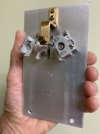
Next was to Nickel plate all the components.
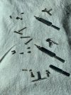
All the parts Nickel plated even a couple of extra pieces for another instrument [ I cannot help myself and it's a GWR instrument ].
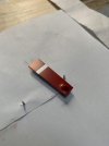
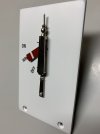
The Signal Arm was sprayed with a etch primer then Tamiya Red and White top coats followed by a Satin clear coat.
The first of two all assembled, the stops for the Signal Arm are pins on these instruments so I didn't have to make any fiddly springs this time.
The face plate was sprayed with a etch primer then a Tamiya lacquer white top coat.
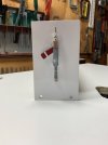
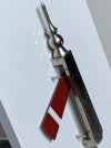
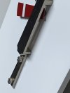
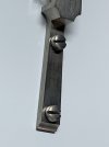
I used Woodlands Scenics dry lettering for the letters, the instrument is fully assembled the mechanism behind the face plate
is in a hole in the work bench to keep the face almost level with the work bench surface.
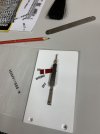
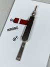
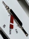
I enjoyed making these Tyers Instruments as they were completely different than the others I have made.
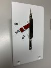
The Mahogany timber cases are still to be made I have drawn plans but my dust extractor needs some modifications
done to it before these can be made.

Next was to Nickel plate all the components.

All the parts Nickel plated even a couple of extra pieces for another instrument [ I cannot help myself and it's a GWR instrument ].

The Signal Arm was sprayed with a etch primer then Tamiya Red and White top coats followed by a Satin clear coat.

The first of two all assembled, the stops for the Signal Arm are pins on these instruments so I didn't have to make any fiddly springs this time.
The face plate was sprayed with a etch primer then a Tamiya lacquer white top coat.


I used Woodlands Scenics dry lettering for the letters, the instrument is fully assembled the mechanism behind the face plate
is in a hole in the work bench to keep the face almost level with the work bench surface.


I enjoyed making these Tyers Instruments as they were completely different than the others I have made.

The Mahogany timber cases are still to be made I have drawn plans but my dust extractor needs some modifications
done to it before these can be made.

michael mott
Western Thunderer
Wow I didn’t realize that the new signal was (just) another piece of your amazing signaling equipment, I thought it was a signal that would be used on the layout.
Superb piece!
Michael
Superb piece!
Michael
Lancastrian
Western Thunderer
Stunning work on the Tyres indicator. You have my complete admiration.
GWR TRACK CIRCUIT INDICATOR MADE BY WALTERS ELECTRIC MFG Co LONDON
David Waite
Western Thunderer
Well the latest news is I cannot do much at the moment and probably not for some time as my right arm is now in a sling due to
damage done to the muscle from over use, which was caused by painting all those pickets and there are still lots to go, and my left arm is also very sore but hasn't got to the stage that the right arm is at which has excruciating pain if I try to move it, so I need to take it easy as I don't want both arms out of action. So what dos'e one do? well we just look for what we can do and my brain is still working at this point and I can push the computer buttons with my left hand so that's something.
I have mentioned before there are a couple of instruments I would still like to make one is a SR SYKES track circuit indicator similar to the ones I have already made the other is a brass cased GWR RE THOMPSON track circuit indicator made to a diameter of 76mm and mounted on its original type of cast metal stand complete with the indicator plate mounted on the top of the instrument.
So today I thought I would make a start on the GWR instrument for something to do so I gathered up all my drawing equipment and started looking through the various photos I have so I can draw a scale plan to work from for when I get better, and I can say I have done well today even though I have rubbed out every line and shape many times over trying to get the proportions and sizes to look correct I'm not expecting to get it perfect but if I can at least get it looking as it should that's more than I could ask for, when I get something worth posting on this I will show you.
Meanwhile here is the story of the GWR Instrument I have made it is still waiting for its timber casing to be made sitting in a box alongside the two TYERS Instruments.
This Track Circuit Instrument is being made to full size and will eventually sit in the space between two of the Block Instruments on the shelf at Pine Oak Junction. These instruments were made by WALTERS ELECTRIC MFG Co of LONDON for the GWR the timber casing seems to be a standard design and were used for different instruments over time with slight modifications where needed.
First to be made was the Signal arm unlike the TYERS signal arm the signal arm on this instrument is Balanced with the weights attached to the arm itself.
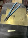
The exact size I required for the two weights were machined out of solid brass stock.
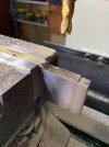
The two weights were cut and soft soldered into place and filed to match the shape of the Arm.
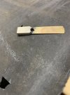
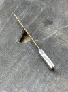
The excess solder was machined off to give a nice square edge along the sides of the weights.
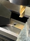
damage done to the muscle from over use, which was caused by painting all those pickets and there are still lots to go, and my left arm is also very sore but hasn't got to the stage that the right arm is at which has excruciating pain if I try to move it, so I need to take it easy as I don't want both arms out of action. So what dos'e one do? well we just look for what we can do and my brain is still working at this point and I can push the computer buttons with my left hand so that's something.
I have mentioned before there are a couple of instruments I would still like to make one is a SR SYKES track circuit indicator similar to the ones I have already made the other is a brass cased GWR RE THOMPSON track circuit indicator made to a diameter of 76mm and mounted on its original type of cast metal stand complete with the indicator plate mounted on the top of the instrument.
So today I thought I would make a start on the GWR instrument for something to do so I gathered up all my drawing equipment and started looking through the various photos I have so I can draw a scale plan to work from for when I get better, and I can say I have done well today even though I have rubbed out every line and shape many times over trying to get the proportions and sizes to look correct I'm not expecting to get it perfect but if I can at least get it looking as it should that's more than I could ask for, when I get something worth posting on this I will show you.
Meanwhile here is the story of the GWR Instrument I have made it is still waiting for its timber casing to be made sitting in a box alongside the two TYERS Instruments.
This Track Circuit Instrument is being made to full size and will eventually sit in the space between two of the Block Instruments on the shelf at Pine Oak Junction. These instruments were made by WALTERS ELECTRIC MFG Co of LONDON for the GWR the timber casing seems to be a standard design and were used for different instruments over time with slight modifications where needed.
First to be made was the Signal arm unlike the TYERS signal arm the signal arm on this instrument is Balanced with the weights attached to the arm itself.

The exact size I required for the two weights were machined out of solid brass stock.

The two weights were cut and soft soldered into place and filed to match the shape of the Arm.


The excess solder was machined off to give a nice square edge along the sides of the weights.

Richard Gawler
Western Thunderer
David, get well soon!
Lancastrian
Western Thunderer
David,
Wishing you a speedy recovery from your injury.
Wishing you a speedy recovery from your injury.
Intercity126
Western Thunderer
Get well soon, David!
David Waite
Western Thunderer
The latest with my arm is I can now move it side ways without pain so I have been using it a little to build up some strength in it.
I couldn't find any photos about the building of the Front Brass Bearing Bracket only the next two photos which show just the round stock being squared off which will become the front Bearing Bracket.
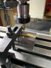
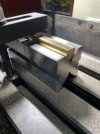
The Aluminium Face plate being machined up.
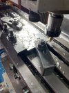
The holes were not drilled all at once but in stages in this way I was less likely to make a mistake.
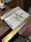
After all the holes on the front of the face plate were completed it was turned over and the remaining holes at the back
completed then the rear Bearing Bracket was fitted.
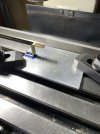
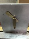
At this point there is no armature attached to the main shaft so I could perfectly balance the Signal Arm by
filing off small amounts where needed so it would stop in any position without moving.
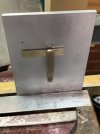
It is actually lower quadrant it is just in this position to show balance as the arm could almost turn a full circle.
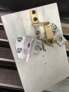
Next the Armature was Silver Soldered to the main shaft and the two coil brackets along with their coils fitted in position.
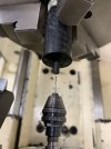
Two spring wire Signal Arm stops were required the small buffers that are fitted to the ends were turned up from
some Black Delrin Plastic and drilled to suit the spring wire.
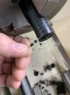
The Spring wire was sourced from this coil spring.
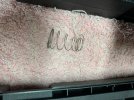
All completed.
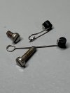
There isn't much room between the Bearing and the Face plate for the hidden spring stop but it has just enough clearance for it to move when the Signal Arm contacts it however I have set the coils in such a position so when the armature rests on them the Signal Arm clears the Delrin
Buffers by a couple of Thou this will prevent damage to the paint on the Signal Arm so basically they are there for show even though they
do work.
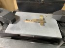
I couldn't find any photos about the building of the Front Brass Bearing Bracket only the next two photos which show just the round stock being squared off which will become the front Bearing Bracket.


The Aluminium Face plate being machined up.

The holes were not drilled all at once but in stages in this way I was less likely to make a mistake.

After all the holes on the front of the face plate were completed it was turned over and the remaining holes at the back
completed then the rear Bearing Bracket was fitted.

At this point there is no armature attached to the main shaft so I could perfectly balance the Signal Arm by
filing off small amounts where needed so it would stop in any position without moving.

It is actually lower quadrant it is just in this position to show balance as the arm could almost turn a full circle.

Next the Armature was Silver Soldered to the main shaft and the two coil brackets along with their coils fitted in position.

Two spring wire Signal Arm stops were required the small buffers that are fitted to the ends were turned up from
some Black Delrin Plastic and drilled to suit the spring wire.


The Spring wire was sourced from this coil spring.

All completed.

There isn't much room between the Bearing and the Face plate for the hidden spring stop but it has just enough clearance for it to move when the Signal Arm contacts it however I have set the coils in such a position so when the armature rests on them the Signal Arm clears the Delrin
Buffers by a couple of Thou this will prevent damage to the paint on the Signal Arm so basically they are there for show even though they
do work.

David Waite
Western Thunderer
A couple more photos just before it was stripped down for painting and the Nickel plating of the various parts.
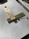
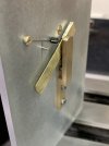
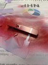
The Face plate was painted white then it was well covered up for the painting of the Signal Arm
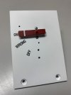
Again I used Woodlands Scenics Dry Transfers for the lettering then a sealing clear coat of Lacquer was sprayed over the top.
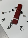
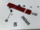
All the components were Nickel plated then joy and smiles when it all comes together.
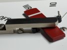
All Finished and tested.
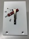
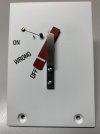
All three Finished Instruments are in a shoe box just waiting for their timber casings to be made.
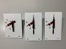


The Face plate was painted white then it was well covered up for the painting of the Signal Arm

Again I used Woodlands Scenics Dry Transfers for the lettering then a sealing clear coat of Lacquer was sprayed over the top.


All the components were Nickel plated then joy and smiles when it all comes together.

All Finished and tested.


All three Finished Instruments are in a shoe box just waiting for their timber casings to be made.

NEW Build / GWR Track Circuit Indicator
David Waite
Western Thunderer
My arm is on the improve however it soon gets sore if I do a little too much and as I can work the lathe and mill basically one handed I have now made a start on my latest Instrument.
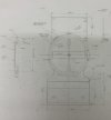
So as promised here is the drawing that I have come up with, I originally drew a drawing almost the same as this one but with no measurements, every item that is on this type of instrument that I could find in photos were drawn in concentrating on getting their individual proportions correct and with each other which is a challenge when photos are taken from all sorts of angles.
The Brass casing diameter is the deciding factor for giving me all the measurements.
I was able to purchase a piece of 76.2 mm OD with a wall thickness of 3.18 mm Brass Tube, so now having a 76mm casing diameter that I could work from I could now scale up a drawing seen below, the measurements are as close as I could get some however will no doubt be wrong but I can alter them as I do the build.
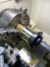
I skimmed off 0.2 mm from the OD to remove the gouge marks that were left on the surface from manufacturing.
I used a 4 jaw chuck for better gripping as less force is needed than a 3 jaw chuck and there is also less distortion to the job,
and to eliminate chatter I used a Pipe Centre.
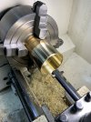
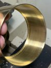
The front edge radius was turned then the tube was bored out to give a wall thickness of 1 mm and a flat square edge machined
inside behind the front radius for the glass to rest upon.
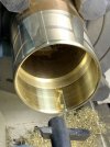
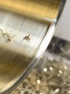
One measurement I could not settle on was the depth of the brass casing so I emailed a heritage railway in the UK after
finding a instrument like the one I am making in a photo of their museum the following day a email was returned with the
the measurements I asked for, what surprised me was the diameter of the prototype at 123mm in diameter I had no idea
they were so large my instrument being at 76mm which is about 1.6 ratio.
So with the measurement at hand I was able to part this off which I did a couple of hours ago.
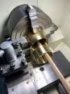
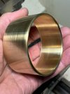
The inner edge of the front radius which the glass will rest upon can be seen in this photo.
So as promised here is the drawing that I have come up with, I originally drew a drawing almost the same as this one but with no measurements, every item that is on this type of instrument that I could find in photos were drawn in concentrating on getting their individual proportions correct and with each other which is a challenge when photos are taken from all sorts of angles.
The Brass casing diameter is the deciding factor for giving me all the measurements.
I was able to purchase a piece of 76.2 mm OD with a wall thickness of 3.18 mm Brass Tube, so now having a 76mm casing diameter that I could work from I could now scale up a drawing seen below, the measurements are as close as I could get some however will no doubt be wrong but I can alter them as I do the build.

I skimmed off 0.2 mm from the OD to remove the gouge marks that were left on the surface from manufacturing.
I used a 4 jaw chuck for better gripping as less force is needed than a 3 jaw chuck and there is also less distortion to the job,
and to eliminate chatter I used a Pipe Centre.

The front edge radius was turned then the tube was bored out to give a wall thickness of 1 mm and a flat square edge machined
inside behind the front radius for the glass to rest upon.


One measurement I could not settle on was the depth of the brass casing so I emailed a heritage railway in the UK after
finding a instrument like the one I am making in a photo of their museum the following day a email was returned with the
the measurements I asked for, what surprised me was the diameter of the prototype at 123mm in diameter I had no idea
they were so large my instrument being at 76mm which is about 1.6 ratio.
So with the measurement at hand I was able to part this off which I did a couple of hours ago.


The inner edge of the front radius which the glass will rest upon can be seen in this photo.

JimG
Western Thunderer
That's some finish when you can see the chuck jaw reflections.

Jim.
David Waite
Western Thunderer
The next part to be made is the Cast Brass Back of the instrument I made this out of Aluminium, it is being made in two pieces as I'm restricted with the thickness of Aluminium material I have, the prototype is of course a one piece Brass casting consisting of a straight upright
section which includes the various shapes and brackets at the top to hold the instrument mechanism on.
The first section I made this week is the straight upright section, seen in this photo is the last of my Aluminium of usable size that would suit
this project, I will be able to cut out a face plate and the rear upright from it.
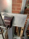
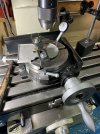
Outlines of the back were drawn in pencil on the Aluminium piece, it was clamped to the rotary table then the fun part starts.
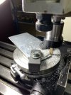
The only issue with rotary tables when doing shapes like these is the clamps need to be moved many times
to gain access to the sections that require machining under them, such is life.
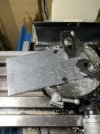
What is actually being machined here is the rear face of the Back, the part you would never see unless you looked behind the Instrument but in
my case it will be seen so I am reproducing it as close as possible,
There is a strengthening rib running around the entire outer edge, the rib seen here being machined is higher than its needed but will be machined down to its correct height at the end.
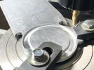
See those clamps are in the way.
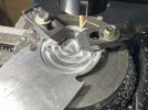
The curves are slightly different than my original plan I changed them to make it look a bit closer to the prototype.
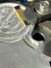
Out with the tools that don't have a digital read out, you can always count on them.
One side done now the other.
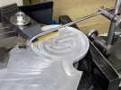
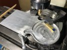
Seen here cutting away all the infill after this was done I sanded the milling lips off and sand blasted the complete rear surface.
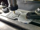
After being sand blasted a couple of blemishes were to be seen here and there but trust me they are now gone, there is still a final
trimming of the outer edge of the circle to be done to bring it to a finish size which will then match the thickness of the other ribs.
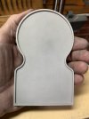
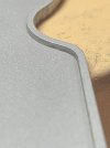
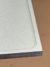
Its dimensions are close to my plan but some are not the same as I have changed some sizes and shapes to make it look a bit closer to the real thing.
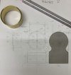
These Instruments have a very odd support not pretty I recon it was more of a after thought than a design they just used a piece of Angle iron that was screwed to the bottom of the Brass Casting then screwed to the Block Shelf through the Angle iron, I have seen two different sizes used with
this type of instrument the original instruments seem to use a larger section angle than the later ones of there same type so my instrument is getting the larger type of Angle iron.
The Angle Iron seen here is the correct thickness but is little too large so this was squared up and machined down to the size I required.
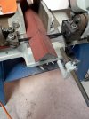
Next all the holes to be drilled and tapped, seen here is the Angle Iron clamped in its position on the front of the Back so as to drill the 4 tapping holes and clearance holes together.
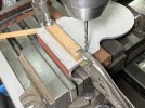
Getting ready for the final trim of the outer circle edge, clocking up using the inner edge of the rib, the height of the
rib has already been reduced to its correct height, yep those clamps are in the way again.
section which includes the various shapes and brackets at the top to hold the instrument mechanism on.
The first section I made this week is the straight upright section, seen in this photo is the last of my Aluminium of usable size that would suit
this project, I will be able to cut out a face plate and the rear upright from it.

Outlines of the back were drawn in pencil on the Aluminium piece, it was clamped to the rotary table then the fun part starts.

The only issue with rotary tables when doing shapes like these is the clamps need to be moved many times
to gain access to the sections that require machining under them, such is life.

What is actually being machined here is the rear face of the Back, the part you would never see unless you looked behind the Instrument but in
my case it will be seen so I am reproducing it as close as possible,
There is a strengthening rib running around the entire outer edge, the rib seen here being machined is higher than its needed but will be machined down to its correct height at the end.

See those clamps are in the way.

The curves are slightly different than my original plan I changed them to make it look a bit closer to the prototype.

Out with the tools that don't have a digital read out, you can always count on them.
One side done now the other.


Seen here cutting away all the infill after this was done I sanded the milling lips off and sand blasted the complete rear surface.

After being sand blasted a couple of blemishes were to be seen here and there but trust me they are now gone, there is still a final
trimming of the outer edge of the circle to be done to bring it to a finish size which will then match the thickness of the other ribs.


Its dimensions are close to my plan but some are not the same as I have changed some sizes and shapes to make it look a bit closer to the real thing.

These Instruments have a very odd support not pretty I recon it was more of a after thought than a design they just used a piece of Angle iron that was screwed to the bottom of the Brass Casting then screwed to the Block Shelf through the Angle iron, I have seen two different sizes used with
this type of instrument the original instruments seem to use a larger section angle than the later ones of there same type so my instrument is getting the larger type of Angle iron.
The Angle Iron seen here is the correct thickness but is little too large so this was squared up and machined down to the size I required.

Next all the holes to be drilled and tapped, seen here is the Angle Iron clamped in its position on the front of the Back so as to drill the 4 tapping holes and clearance holes together.

Getting ready for the final trim of the outer circle edge, clocking up using the inner edge of the rib, the height of the
rib has already been reduced to its correct height, yep those clamps are in the way again.

James Spooner
Western Thunderer
David,The next part to be made is the Cast Brass Back of the instrument I made this out of Aluminium, it is being made in two pieces as I'm restricted with the thickness of Aluminium material I have, the prototype is of course a one piece Brass casting consisting of a straight upright
section which includes the various shapes and brackets at the top to hold the instrument mechanism on.
The first section I made this week is the straight upright section, seen in this photo is the last of my Aluminium of usable size that would suit
this project, I will be able to cut out a face plate and the rear upright from it.
View attachment 211730
Outlines of the back were drawn in pencil on the Aluminium piece, it was clamped to the rotary table then the fun part starts.
View attachment 211732
The only issue with rotary tables when doing shapes like these is the clamps need to be moved many times
to gain access to the sections that require machining under them, such is life.
View attachment 211733
What is actually being machined here is the rear face of the Back, the part you would never see unless you looked behind the Instrument but in
my case it will be seen so I am reproducing it as close as possible,
There is a strengthening rib running around the entire outer edge, the rib seen here being machined is higher than its needed but will be machined down to its correct height at the end.
View attachment 211734
See those clamps are in the way.
View attachment 211735
The curves are slightly different than my original plan I changed them to make it look a bit closer to the prototype.
View attachment 211736
Out with the tools that don't have a digital read out, you can always count on them.
One side done now the other.
View attachment 211737
View attachment 211738
Seen here cutting away all the infill after this was done I sanded the milling lips off and sand blasted the complete rear surface.
View attachment 211739
After being sand blasted a couple of blemishes were to be seen here and there but trust me they are now gone, there is still a final
trimming of the outer edge of the circle to be done to bring it to a finish size which will then match the thickness of the other ribs.
View attachment 211740
View attachment 211741
View attachment 211742
Its dimensions are close to my plan but some are not the same as I have changed some sizes and shapes to make it look a bit closer to the real thing.
View attachment 211743
These Instruments have a very odd support not pretty I recon it was more of a after thought than a design they just used a piece of Angle iron that was screwed to the bottom of the Brass Casting then screwed to the Block Shelf through the Angle iron, I have seen two different sizes used with
this type of instrument the original instruments seem to use a larger section angle than the later ones of there same type so my instrument is getting the larger type of Angle iron.
The Angle Iron seen here is the correct thickness but is little too large so this was squared up and machined down to the size I required.
View attachment 211744
Next all the holes to be drilled and tapped, seen here is the Angle Iron clamped in its position on the front of the Back so as to drill the 4 tapping holes and clearance holes together.
View attachment 211745
Getting ready for the final trim of the outer circle edge, clocking up using the inner edge of the rib, the height of the
rib has already been reduced to its correct height, yep those clamps are in the way again.
View attachment 211746
Your posts never cease to amaze me; you are an absolute artist with the machine tools!
Nigel
Threadmarks
View all 19 threadmarks
Reader mode
Reader mode

