A Layout Called CHIMTONSTOKE

David Waite

Western Thunderer
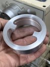
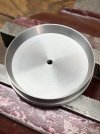
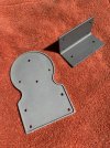
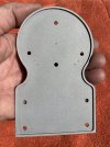
All the holes are done and the Aluminium Back trimmed to its finished size.
IMG_2457.jpeg


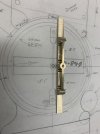
The two outer most holes in the circle section are for the wires to enter the instrument, the four small partly recessed milled holes are representing
the ends of screws finishing in tapped holes entering from the other side, these screws two per side held a screw terminal
to the back that the line wires attached to and the enamel wires from the coil connected to, the top hole and lower hole were originally
there to hold the instruments mechanism to the back but I am using these holes to hold the second section of Aluminium to the back
and as for the little hole in the middle I have no idea it is there on the prototype so I drilled it, maybe a oil hole for the rear bearing?.
IMG_2461.jpeg


Next is the second half of the back to be made this piece of Aluminium is 86mm x 86mm and is 25mm thick
IMG_2490.jpeg


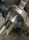
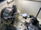
The block was turned down to a diameter slightly larger than the outer circle diameter of the back piece already made.
IMG_2492.jpeg


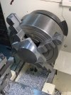
The block was spun around to start the machining the only reason I am still using the 8"four jaw chuck is
my three jaw chuck was at its limit and this was a safer way to go.
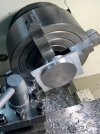
IMG_2496.jpeg


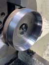
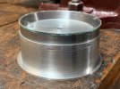
Most of the main turning is done the section under the jaws still needs to be thinned down.
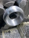
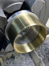
IMG_2519.jpeg


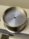
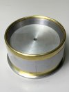
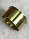
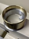
A trial fit of the Brass Casing when the piece under the jaws is turned a little more the Brass Casing will slide
further along.
IMG_2520.jpeg


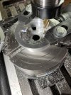
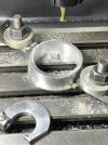
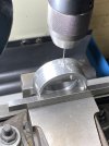
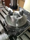
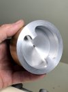
On to the mill for the next stage shown here are sections of the inside of the back flange being cut away this is to allow clearance for the mechanism leaving behind two protruding block pieces these will have tapped holes in them for the two screws to attach this Aluminium piece to the Aluminium Back.
IMG_2531.jpeg


IMG_2533.jpeg


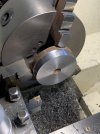
Back to the lathe and this time clamped in the three jaw chuck to turn the flange a little more there is still some turning to
be done to the piece that is left but due to its shape being easily damaged I will leave it to last.
IMG_2547.jpeg


IMG_2554.jpeg


The Aluminium piece will need to be machined down a little once I decide on what thickness of glass I will be using.
IMG_2559.jpeg


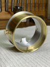
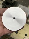
A face plate was turned up with a slide fit into the brass casing.
IMG_2570 2.jpeg


IMG_2571 2.jpeg


There is no plan for this part of the build I'm just working it out as I go along, so far so good.
IMG_2573 2.jpeg
 

David Waite

Western Thunderer
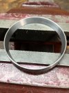
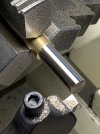
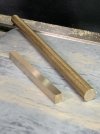
Next part I made was the Tapered spacer ring that sits between the glass and the face plate I finally used up my largest
piece of solid round steel stock I'm glad to see it all used up but wish I still had it for other things.

Trimmed down to the correct OD and faced off.
IMG_2581.jpeg


Bored out parallel to the smallest diameter of the taper.
IMG_2582.jpeg


I cut the taper to the 8mm depth starting 1mm in from the outer front edge.
IMG_2585.jpeg


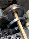
Parting off.
IMG_2587.jpeg


IMG_2590.jpeg


The test all ok.
IMG_2592.jpeg


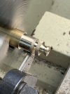
I wanted a change of pace so I turned the Two Brass Thumb screws.
I turned the diameter then ran the knurling tool along
IMG_2595.jpeg


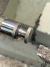
I turned the shapes, drilled and tapped a 1/8"WW threaded hole in the end for the brass screw thread to fit in then parted it off.
IMG_2622.jpeg


The stock left in the chuck was drilled and tapped so it could hold the piece for facing it off.
IMG_2642.jpeg


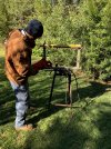
I don't know why I never thought of this idea of cutting the glass before the idea just came from nowhere into my head when I was laying in bed thinking about what sequence of events I need to do on the instrument for the next days progress so here is my invention.
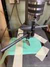
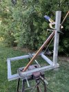
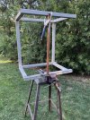
I removed the Diamond cutting head off my glass cutter I then bent up a piece of very hard rod and screwed it tightly into the diamond head I then removed the cutting blade off my adjustable hole cutter and with a washer fitted the rod in its place, next I removed the V belt off the pedestal drill and by turning the extension of the hole cutter and at the same time with light pressure on the down feed spindle hey presto a perfect scribed circle

IMG_2736.jpeg


See it works, the lovely scribed circle is still there but the roughness was done by the pliers chipping away the unwanted glass bits it won't be seen so it doesn't matter.
IMG_2737.jpeg


Now that I had the glass thickness at hand I could trim the back Aluminium piece to its correct length allowing a few thou movement for the glass.
IMG_2739.jpeg


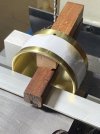
All assembled to check the fitting of the parts, this completes the building of the major parts for the instruments casing.
IMG_2742.jpeg
 

David Waite

Western Thunderer
Next the Brass Casing had its clearance holes drilled for the two Thumb screws
IMG_2776.jpeg


The Brass Casing was used as a template to mark the position of the holes to be drilled into the Aluminium, the two dowels
keep everything at right angles for this.
IMG_2778.jpeg


Tapped 1/8 WW
IMG_2781.jpeg


IMG_2785.jpeg


IMG_2788.jpeg


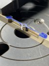
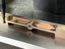
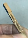
The next job is to make the Bridge Bearing with its imitation Jewel, I machined a square block out of some round stock a little bigger than I need,
it is always nice to know there is that extra metal there just in case, and yes I needed it, I will explain,
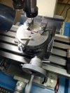
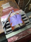
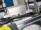
After clocking up the Rotary Table I then clamped the Brass stock to it and squared it up to the milling bed and locked the R/Table up tight, I then started to machine the shape of the Jewel and the screw heads so far so good BUT my eyes the way they are I have to concentrate hard on the machining part of the process and when I accomplished what I wanted to do I naturally looked at the DRO and found it wasn't zero on the X axis it had moved to 0.0700 mm from zero which meant some part of the machining was out so turned it up side down as this can be machined off later this way I had a new surface to start again on.
Now what moved I have no idea I realise the machine is slightly worn as I have done some some heavy work with it over the time and it was never designed to do fine work so I work it accordingly however it shouldn't have moved, the main spindle bearings are worn so I keep the idler to spindle belt tight which over comes this and I keep the spindle lock tight but allowing just enough movement when the Z axis is to be used, anyhow I removed the Gibbs on both the X & Y axis lifted the bed and cleaned it oiled it and reassembled it, no problems there the only thing I can think of is I am running the machine at its maximum spindle speed about 2500 RPM which is driven by a 2HP motor this causes a slight vibration that might have settled something into a different position even though it was all locked up. so its take two I do have enough brass if take 3 or 4 is needed but I'm not sure about my patience will extend to take 4.
IMG_2832.jpeg


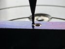
2.5MM diameter cutter.
IMG_2894 2.jpeg


1MM diameter cutter and powered by a 2HP / 1.5KW Motor [now that's efficient no global warming here]
IMG_2899.jpeg


For me this was Eye strain plus.
IMG_2908.jpeg


The only reason the Rotary Table is being used is for the two curved sections around the centre bearing, all measurement's are taken
and zeroed from this position and the job is squared parallel with the milling table as I never go by the degree markings on the R/T.
IMG_2920.jpeg


First pass another 0.25mm has to come off to be on size and the DRO is still reading 0.0000 yippee, this is a slow process with such a slow spindle speed for these tiny cutters.
IMG_2917.jpeg
 

jonte

Western Thunderer
Next the Brass Casing had its clearance holes drilled for the two Thumb screws
View attachment 213170


The Brass Casing was used as a template to mark the position of the holes to be drilled into the Aluminium, the two dowels
keep everything at right angles for this.
View attachment 213171


Tapped 1/8 WW
View attachment 213172


View attachment 213173


View attachment 213174


The next job is to make the Bridge Bearing with its imitation Jewel, I machined a square block out of some round stock a little bigger than I need,
it is always nice to know there is that extra metal there just in case, and yes I needed it, I will explain,
After clocking up the Rotary Table I then clamped the Brass stock to it and squared it up to the milling bed and locked the R/Table up tight, I then started to machine the shape of the Jewel and the screw heads so far so good BUT my eyes the way they are I have to concentrate hard on the machining part of the process and when I accomplished what I wanted to do I naturally looked at the DRO and found it wasn't zero on the X axis it had moved to 0.0700 mm from zero which meant some part of the machining was out so turned it up side down as this can be machined off later this way I had a new surface to start again on.
Now what moved I have no idea I realise the machine is slightly worn as I have done some some heavy work with it over the time and it was never designed to do fine work so I work it accordingly however it shouldn't have moved, the main spindle bearings are worn so I keep the idler to spindle belt tight which over comes this and I keep the spindle lock tight but allowing just enough movement when the Z axis is to be used, anyhow I removed the Gibbs on both the X & Y axis lifted the bed and cleaned it oiled it and reassembled it, no problems there the only thing I can think of is I am running the machine at its maximum spindle speed about 2500 RPM which is driven by a 2HP motor this causes a slight vibration that might have settled something into a different position even though it was all locked up. so its take two I do have enough brass if take 3 or 4 is needed but I'm not sure about my patience will extend to take 4.
View attachment 213175


2.5MM diameter cutter.
View attachment 213176


1MM diameter cutter and powered by a 2HP / 1.5KW Motor [now that's efficient no global warming here]
View attachment 213177


For me this was Eye strain plus.
View attachment 213181


The only reason the Rotary Table is being used is for the two curved sections around the centre bearing, all measurement's are taken
and zeroed from this position and the job is squared parallel with the milling table as I never go by the degree markings on the R/T.
View attachment 213182


First pass another 0.25mm has to come off to be on size and the DRO is still reading 0.0000 yippee, this is a slow process with such a slow spindle speed for these tiny cutters.
View attachment 213183
Quite simply a superior level of modelling, David.
Thank you for sharing.
Jon
 

David Waite

Western Thunderer
We have had so much going on over the last week or so I haven't been able to do much on my instrument, however I have been in the shed but doing other things one of them was to make a new spout for the oil can so I can oil the machines the old spout had worn out and wasn't pushing the ball bearing in on the oil points around the machines, the new one dose. The other thing that has taken away some modelling time this week was the front fence my arm has improved enough to enable me to start putting some pickets on the fence the weather is too cold for painting now and the nights are getting damp so I figured if I put as many as I can on before winter sets in I can paint the last coats on them next summer while they are in position on the fence so this week we managed to get 60 pickets on, that a start.

With the little time I had, this is what I got done.
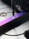
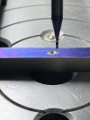
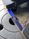
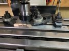
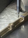
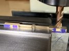
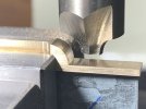
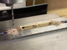
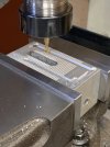
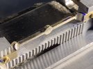
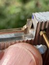
I cut away the baulk of the brass with a 4mm cutter shown in this photo.
IMG_2945.jpeg


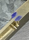
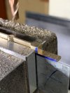
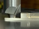
I then changed to a 2mm cutter to give a smaller radius in the corners and to machine the two thin arm pieces to their final finish size.
IMG_2951.jpeg


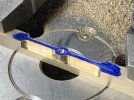
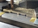
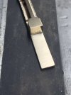
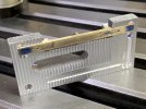
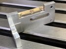
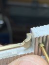
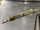
Next was to machine square the radiuses and machine the two thin arms to their finish length.
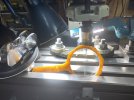
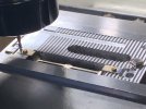
I clamped two pieces of sheet metal to the bed to act as a positioning jig so once the job was centred it could be flipped over
and the opposite cuts would be in the exact opposite position
IMG_3007.jpeg


IMG_3008.jpeg


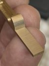
The outside of the centre circle still needs to be squared where it meets the two arm sections, this I will need to do by eye,
i'm not looking forward to that.
IMG_3016.jpeg
 

David Waite

Western Thunderer
I give up putting comments on here because i've run out of words to compliment your workmanship David

Ken
I normally give a Like in response to the many kind comments that the members have given me over the time ‘which I appreciate enormously’ but you running out of words I must say thanks Ken and of course a Like.
David.
 
Top