A Layout Called CHIMTONSTOKE

David Waite

Western Thunderer
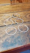
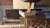
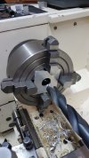
The next items to be made were the six Flange Rings for the rear of the casings, these I made out of Aluminium and bored their ID to give a Interference fit onto the OD of the Brass casings at their rear edge.

The Aluminium plates were drilled and then bored.
20201029_160019 (1).jpg


The corners of the Aluminium plate were cut off by hacksaw then turned down to the required size.
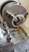
20201031_151714 (1).jpg


I find a parting tool is as good or better than a machine bit for Aluminium when light pressure is required so as not to move the job and also gives a great finish, any pressure on the rings by the jaws of the chuck would cause their distortion so they were held by what I call a loose clamping force.
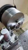
20201031_142041.jpg


All done
20201101_115536 (1).jpg


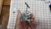
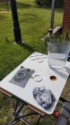
One face of each Flange Ring was cleaned up on some wet and dry to remove any imperfections then a coat of Etch primer applied followed by a top coat of Semi Gloss Black. The Brass Casings were given a final polish and degreased with some Prepcoat the Flange Rings were then pressed on to the rear of their casings then each Casing was heated in the oven then a couple of coats of a Brass Gloss clear coat applied to stop tarnishing and keep them shiny.
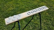
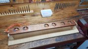
The round hole that can be seen in the board was for the mechanism of a instrument to sit into and being supported by its Face plate on the surface of the board, this is how I held them while working on the face plates during various stages of their assembly.
I don't know how I managed without my Black & Decker Work Mate in the days of old.
20201208_091956 (1).jpg
 

David Waite

Western Thunderer
The next stage was the painting of the faces,
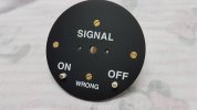
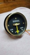
I Air Brushed the faces using a Tamiya Solvent based Acrylic paint in semigloss, the Lettering was done using Woodland Scenics Dry Transfer Decals, these are what I would call a poor product the letters are not crisp, they look good on the sheet they are supplied on but when applied to a surface colour that makes them stand out they soon reveal their faults, when I built the Block Instruments in 1996 the Dry Transfers I used then were made by DECAdry and were perfect in every way and are still there to this day even without a clear coat on them, however all good things come to a end and DECAdry is no longer available and so the closet I could obtain was the Woodland Scenics product so I used them.
From what I have seen there are no two Sykes Instruments that have same shape Letters on their Faces, its my belief that these Letters on the Prototype ones were painted by hand with a brush by different people which has the affect of making the same words a different length and a different overall shape & appearance.


The spacer Rings and the 6 Faces in Etch Primer.
20201010_104615.jpg


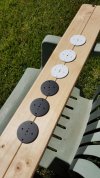
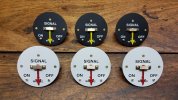
3 Black Distant Signal Faces & 3 White Stop Signal Faces
20201011_154433 (1).jpg


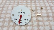
The Coil Brackets were mounted along with the rear brass Bearing Bracket to the rear of the Face Plate which are held in place by the top and two side Brass counter sunk screws, the lower screw is a dummy but its rear projection along with its nut are what a spring clip will catch onto which holds the instrument in place on its mounting board. The two Needle Stops can be seen fitted in position the Complete Face had a Semi Gloss Clear Coat applied to hold the Dry Transfers in place the coat turned out more to a Flat appearance than Semi Gloss just a slight Sheen.
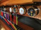
20201122_114940 (1).jpg


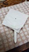
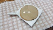
Next the Main Shaft was put into position in the rear Bearing, soft Tissue paper was cut and put over the Face to protect it , a piece of plastic with a slot cut in one end was pushed onto the Armature with a pointer at the other end which you can see, this is to align the Needle in relation to the Armature when the Needle is being soldered to the Main Shaft.
20201127_164803 (1).jpg


The Needle is aligned with the plastic pointer ready for soldering.
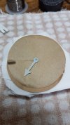
Three pieces of brown paper were placed over the Tissue with their cuts placed at different positions these I replaced a couple of times with fresh ones.
20201127_165155.jpg


The Needle has been soldered in position and sprayed with a etch primer then lifted clear of the Brown paper a little to spray the underside of the Needle.
20201127_171505 (1).jpg


The 3 Stop Instrument Needles getting their top coat.
20201128_123541 (1).jpg


Ready for assembly.
20201128_134405 (1).jpg


First one Done.
20201128_150526 (1).jpg


Getting there.
20201128_150418.jpg
 

David Waite

Western Thunderer
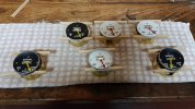
The next photo shows the Spacer Rings being fitted, these were placed in their correct position on the Face and were tacked in this position with three small dabs of Neutral Cure grey Silicone which can be seen on the three lower instruments in this photo, once dry a full bead of Silicone was run around the Spacer Ring giving a permanent fixing to the Face plate.
20201128_163633 (1).jpg


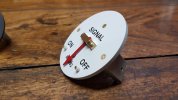
On the outside of the top of each Instrument is a Thumb screw this holds the Instrument on the Timber mounting board it passes through the Brass Casing and then passes through a Aluminium bracket that supports the Instrument which is against the inside of the Brass Casing at the top. The thumb screw then screws into a Brass bracket that is screwed to the Timber mounting board, the Aluminium bracket is seen being made in this photo.
20201206_094458.jpg


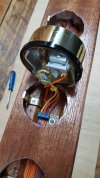
The Aluminium Bracket supports the Mechanism by being screwed to one of the coil brackets which is shown being tapped in the photo for this purpose.
20201206_132636.jpg


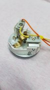
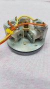
The Aluminium Bracket is in position and the Coils are wired with tails, one supply for each coil and a common return for both.
20201217_191542 (1).jpg


The lower Dummy face screw-nut can be seen between the coils.
20201217_191622.jpg


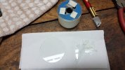
Next six pieces of glass were cut I used a hole saw as a template which gave the correct Diameter, I put three pieces of soft sticky tape on the underside of the hole saw to prevent it scratching the glass.
20201203_141123 (1).jpg


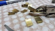
This photo shows the lower 'Spring' Brass bracket being made the two pieces that make up each spring bracket are riveted together by small brass rivets I made, the reason for the rivets is because no heat could be applied by soldering ect or the spring of the brass would be lost.
20201205_143516 (1).jpg


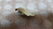
A finished Bracket,
The V Notch seen is positioned under the lower Dummy face screw - nut .
20201205_144210 (1).jpg


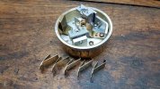
The mechanism in position,
The Spring bracket is positioned under the lower Dummy face screw- nut then is pushed inwards towards the face bending the spring brass bracket in tension so it catches into the 'square hole that the original pressure gauge pipe mounting passed through on the casing.
The section of the Brass bracket that can be seen extending beyond the rear of the casing hooks onto the Timber Mounting board holding the Instrument Firmly in position.
The square hole allows air to move into the mechanism as the coils will run about 45C so this is why I didn't block it off and as it is on the underside it cannot be seen, I fitted a small wire gauze over the hole on the inside to stop crawling bugs making a home.
20201205_153348 (1).jpg
 

David Waite

Western Thunderer
The first one finished.
20201217_192822 (1).jpg


The Mounting board showing the Brass Instrument supports and all wired to a terminal block behind each Instrument, there are two boards
screwed together the rear one having a channel machined out of it for its entire length this is for the cables to pass through and then exit at the L/h end.
20201216_204803.jpg


Tails fitted into the terminal block.
20201217_193506.jpg


All done and the UP MAIN Distant is pulled off .
20201217_202336.jpg


The UP Train is still on its way.
20201217_202502.jpg


This view shows the wiring exiting the channel these wires will enter a support leg that holds the block shelf up then travel downwards
to the underside of the base board.
20201218_183554 (1).jpg


Next step the Train room.
20201218_183614.jpg
 

David Waite

Western Thunderer
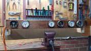
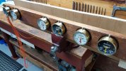
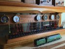
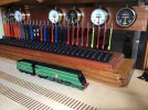
Mounted in position sorry for the slightly out of focus photo.
IMG_0865.jpeg


At some stage I will make small oval number plates to identify which Signal each Repeater Instrument is referring to and they will be fixed to the timber directly below each Instrument.
IMG_0918.jpeg


IMG_0872.jpeg


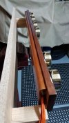
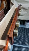
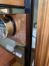
The two brass 3/16" counter sunk screws that support the Instruments were screwed into tapped holes in the RHS.
IMG_9091.jpeg


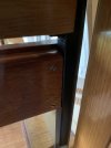
This shows a rear view of the LH end of the rear Trenched timber, the wires exit the trench and then enter through a hole I cut in the RHS for the 13 wires to pass downwards to the underside of the baseboard.
IMG_9090.jpeg


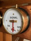
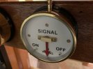
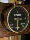
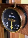
Stop Signal Repeater.
IMG_9126.jpeg


IMG_9150.jpeg


Distant Signal Repeater.
IMG_9138.jpeg


IMG_9130.jpeg


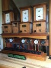
It took 4 months to build them from September to December 2020 my goal was to have them in place by Christmas day and I did.
IMG_0963.jpeg
 
SIGNAL BOX DIAGRAM for PINE OAK JUNCTION

David Waite

Western Thunderer
The latest project for my layout is a Signal Box Diagram for Pine Oak Junction, it is all hand drawn and coloured using water colour paint.
This project is something that I had been thinking to do for sometime but could never find the right time to start, after the six Sykes Instruments were finished and then the 3 mechanisms for the next repeater instruments were done my mind was clear to finally begin.
The drawing of this Signal Box Diagram, was for me a personal challenge I knew in the back of my mind I had the ability to draw it even though I had never done the likes of it before, the challenge for me was being able to see.
The world now days is blurred for me without my glasses, these allow me to see only the day to day things and because of things called floaters inside my eyes I miss out on random portions of my vision, however I have a magnifying head piece that can hold two magnifying clip on lenses of different powers which I can wear in front of my glasses, I change different lens powers depending on what I'm doing with this I have been able to accomplish many things like the Lever Frames & Repeater Instruments it wasn't easy but I got by.
The drawing of the Diagram has a lot of free hand involved which isn't easy when one cannot see good, the first stage was drawn in pencil this was ok as mistakes and alterations which there were many could be rubbed out, however it became nerve- wracking when I had to ink over all the pencil lines with a permanent ink as a mistake could not be removed so what ever I did I had to get it correct the first time only.
I met this challenge with a open mind and I'm so pleased with what I accomplished I started the project in March 2022 and finished it on the 13 March 2023, I worked on it bit by bit when ever I had time throughout the year, there were of course other things involved with the making of this Diagram that also took up some of this time.


The Signal Box Diagram.
My favourite style of Signal Box Diagrams are the ones that were drawn in the 1890s and some up to around 1910 these are the years which my one is based on. Most railway companies and railway signalling contractors from my own observations tended to copy each other within periods of the railways history, diagram styles changed over the years due to the design of the older Diagrams not being able to cater for modern equipment that was part of a more modern railway.

It took me each night over 3 weeks to sketch a shape of a plan that reflected the overall shape of the track work in a simplified way, many pieces of paper were consumed over this time. I made a drawing board many years ago but the top was too small so I attached a piece of melamine big enough to do the job on top, to this I sticky taped down some tracing paper which was the same size as the Diagram I wanted allowing for a margin and the timber frame, the frames outside dimensions are 995mm x 440mm with a face width of 40mm
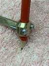
After copying the sketch from the paper and increasing its size onto the tracing paper I released I needed a compass that could draw a radius of up to 300mm, my old Staedtler could never do that and what's more the compass needed to hold a pencil that used a 0.3 mm lead and also the tapered casing of a permanent ink pen so the solution for this was to make a compass.

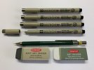
The Ink pens and pencil I used.
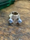
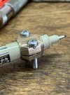
The Pigma Micron are an Archival permanent fade proof ink pen the clamping area has a slight taper.
The 0.3 lead pencil is parallel but slightly larger in diameter.
IMG_E9376.jpeg


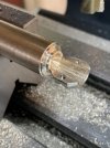
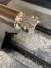
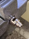
I turned up the pen clamp in the lathe then cut it in half then finished it off in the mill.
IMG_3746.jpeg


As can be seen the screw holes just made it, the diameter of the stock was the largest I had but it worked out ok as
the size of this clamp had a nice feel to it when the compass was being used if it hade been any larger it may have been cumbersome.
IMG_3747.jpeg


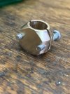
The two Philip headed metric screws worked a treat I thought they might have been a nuisance to use but they worked prefect.
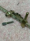
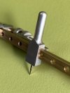
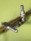
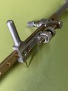
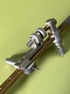
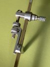
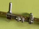
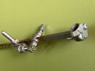
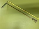
The flat rear view of the clamp is where the long Radius Arm is silver soldered to this arm is made from a piece of 6mm x 3mm brass 530mm long it has 43 x 3mm indexing holes drilled along its length at 10.0000 mm centres these indexing holes is what a locking pin on the sliding assembly locates into. This sliding assembly has the needle and its fine adjustment to move it and lock it at any position between each pair of indexing holes along the length of the radius arm.
IMG_3748.jpeg


IMG_3750.jpeg


The clearance around the screws allows the brass clamp to follow the taper of the pen and tighten without movement.
IMG_3754.jpeg


The clamp attached to the Arm.
IMG_3842.jpeg
 

David Waite

Western Thunderer
This piece being made is the Indexing Lock it was made in two pieces each half having a milled slot to suit the Radius Arm
the two pieces were then Silvered Soldered together then as seen here being machined up to look nice.
I enjoyed building this Compass so much I forgot to take any more photos after this one it wasn't until the parts were done I realised.
IMG_3838.jpeg


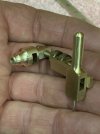
The Indexing pin can be seen here it screws into the Indexing Lock and the plain shank locates in the Radius Arm with a smooth
firm hold and with only light finger pressure.
IMG_3847.jpeg


The the Plain Shank of the Indexing pin travels through the Radius Arm and slightly into the hole that can be seen.
IMG_3849.jpeg


All ready for Nickel plating.
The Needle Handle piece was milled as two seperate pieces then Silvered Soldered together as one piece
then turned up on the lathe.
IMG_3848.jpeg


I Nickel plated the components in a Jam jar, the Needle was from one of my children's old unused school plastic Compass.
IMG_9407.jpeg


IMG_9408.jpeg


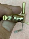
The Knurled Thumb wheel in the Fork of the bracket is for the fine adjustment, the other
Thumb wheel is the Lock and is shown unlocked and backed off the fork in this photo.
IMG_9409.jpeg


The fork is made from 3 pieces of Brass Silvered Soldered together.
IMG_9410.jpeg


IMG_9413.jpeg


IMG_9400.jpeg


The reason I Nickel plated the end of the Radius Arm & clamp and the other parts was to stop the Brass oxidation getting on my fingers.
IMG_9403.jpeg


The Compass can draw a radius starting from 100mm and up to 525mm.
IMG_9428.jpeg
 
Top