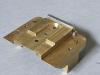
Anne and me in 7mm from the D.A. kit.

OzzyO

Western Thunderer
Hello all I thought that I had this thread going on here as well as over on **web but I don't if any one wants to see what I'm up to on the build this link should take you to it.
http://www.rmweb.co.uk/community/index.php?/topic/70310-anne-and-me-from-the-das-kit-in-7mm/

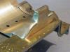
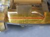
When I started to have a look at the fit of the steam pipe casings in the kit I was not that impressed with them, as something just looked wrong.
100 029a.jpg
The build up to now, I've still got a lot of work to do on her.
100 028.jpg
This is a copy of my last post on **web.

well I did have a day out at the N.R.M. looking at drawings for Anne and some other things. Out of all the drawings that I looked at I decided to buy two and also get them on C/Drom as well a very quick way to spend £100.00 but the drawings are about 3'6" X about 7' clear as a bell to read but a bu99er to work on at that size. I think that if I get any more drawings from them I'll just get them on C/Droms in future. The N.R.M. has a good number of drawings for Anne but the one drawing that is not in the collection as far as I can see is the following one. D52-21040 Steam pipe casing at smokebox. If any one knows of this drawing I would be most grateful to see it or get a copy of it (any cost would be reimbursed).

As I mentioned in one of my last posts about the position of Anne's front footsteps being next to the hanging plate, when you look at this drawing you can see that the footsteps are only 1/2" outside of the buffer beam, not like in that photo. In the same drawing it looks like the running plate was going to be open like on the latter Duchesses as the curved part is not drawn in and the small step is mounted onto the side of the frames.
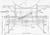
copyright 004.jpg

Now onto the reason that I bought these two drawings, the front steam pipe casings. Using this one I should be able to work out the corner radii, all of the bolt spacings (that will be simple), and approx length of the casing.
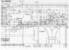
copyright.jpg
This one is the same as the one above but with less clutter.
copyright 001.jpg

On to the side view, at first I was trying to think what the two extensions were above the main casing, then it clicked they're the flange for the mounting bolts. The dip in the top edge I'm not so sure about (any ideas let my know), you can also see how high up the top part of the casing goes up the smokebox (the line just above the top is the smokebox centre line). So apart from showing the steam pipes we now know what is behind the casings.
copyright 002.jpg

This one is very good in that it shows the full width of the casings from the rear, it looks like the main part of the casing is just about above the outside cylinder line and that the main part was vertical. Could it have been made this way just in case they needed to fit smoke deflectors at a later date? It will also come in very handy when I come to start fitting the oil-boxes at a latter date. The only down side to these last two drawings is that there are no dimensions shown, but I do know that the dimension between the frames is 4'11/2" and that the smokebox radius was 3'1" I'll have to check whether inside or outside. The side view will be a bit harder to work out the dimensions on.
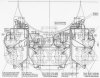
copyright 003.jpg
All drawings are copyright to the N.R.M. and only used for information purposes.

All in all a lot of very useful information. Was it worth the £100.00? time will tell.

OzzyO.
 

OzzyO

Western Thunderer
Hello all,

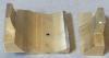
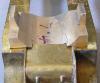
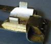
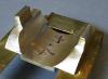
after a bit of time working out the dimensions of the steam pipe casings some of the sizes are a bit "out", to give a few the length of the casting is 37mm when it should be 39mm, the hight of the steam pipe on the casting is 15.5mm when it should be 16.8mm. I think that you can get the idea. To try and show what I'm saying these two photos may help.

post-8920-0-20992100-1435534055_thumb.jpg

post-8920-0-95591700-1435534062_thumb.jpg

I know that these are not the best but it may help to see the problems.

The drawing may have also shown up another problem at the front end, in that the inside valve chest cover could be too high and that will effect the hight of the smokebox and boiler and also the fit of the smokebox and the steam pipe casing (more fun).

Talking about the front casing, the way that I'm thinking about making it is like this. Take a length of 1" and fix it to the bottom of a length of brass that will cover the length and width, then add some more brass to get to above the hight of the main casing then add two more bits of brass for the top steam pipes. All of this will be screwed and soldered together. I'm thinking about using the oven set at 250 Degs. to do this (when the wife is out), Has anyone had a go at this? Then it will be a lot of milling, filing and cursing. Then all I have to do is make the thin (10 or 12 thou) overlays that have the nuts/rivets on them.

Thanks Dave I did see where the dimension was for, the outside of the smokebox.

OzzyO.
PS. more brass to order.
 

OzzyO

Western Thunderer
Hello all,


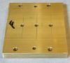
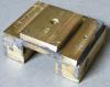
over the last few days I've been working out the sizes for Anne's steam pipe casing and have now started cutting bits of metal.the first bit is the base of the casing, when the time comes to M/C it most of this will be cut away.

post-8920-0-74682700-1436173136_thumb.jpg


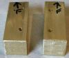
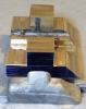
The next part is the bit that will fit between the loco main frames, as quit a bit of this will be cut away I decided to add screw fixing at each corner as well as down the middle. When I came to fit this to the last part that's when the fun started. I had bought some counter sunk brass for this job but when I came to screw them in the tapped holes the bu99ers would not fit, as I don't normally have many C/S screws in stock a bit of head scratching was called for. In the end I used some cheese heads in the counter sinks.

post-8920-0-33228100-1436173152_thumb.jpg


The top parts for the casing, due to what happened above I had to change how I was going to fix these. What I came up with was 6BA cheese head brass screws As I did not fancy tapping all the way through this bar (9/16") I counter bored the top part of the holes.

post-8920-0-21104500-1436173171_thumb.jpg


All the main parts laid out.

post-8920-0-81193100-1436173198_thumb.jpg


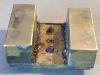
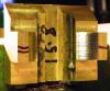
The basic casing made up before cleaning up. For soldering this job up as I had some nice big flat surfaces I decided to use something that I don't normally use "solder paint". Then I filled in the four holes in the square bar with 188 deg. solder.

post-8920-0-02468800-1436173218_thumb.jpg

post-8920-0-59403700-1436173241_thumb.jpg


and from underneath front, as you can tell all of the edges have still to be cleaned up.

post-8920-0-88000100-1436173257_thumb.jpg


from the rear.

post-8920-0-52159700-1436173279_thumb.jpg


What to do next? I think that I'll mark out the profile of the casing on one side, then start making brass chips. One of the last jobs will be M/Cing the saddle shape for the smokebox. Then it will be a lot of filing.


OzzyO.


PS. out of interest I decided to weigh the thing , at the moment it weighs in at 302 grams. I'll have to try and remember to weigh it when it's finished.

PPS. I hope that the photos have copied over.
 

OzzyO

Western Thunderer
Hello all,

after a bit of milling today these are the sort of thing that I ended up with. First the sides and the front end milled to size, this also reduced the weight down to 252 grams. a reduction of approx. 50 Grams. or approx. 2 oz for us old bu99ers. As you can see I've also marked out the top of the steam pipes, the step in the steam pipes and how the front and rear should look. Approx.

post-8920-0-79975100-1436220516_thumb.jpg


A close up of the marking out.The rear angle looks out but it's correct to the drawing, honest.

post-8920-0-03549400-1436220542_thumb.jpg


Milling off the top face, in the old days when I was working in a big M/C shop this was called splitting the pops, if someone was cr4p at working on a mill he would get called that he could not work to a chalk line (not a very nice thing to have to be called behind your back). I've still got about .1mm to remove in this photo. When I check it I was about 0.05mm out, working to a scribed line I would say that's OK

post-8920-0-13839400-1436220835_thumb.jpg


Then it was onto removing the metal from the front and back of the steam pipes, I sure that I took a photo when I'd only removed the metal from the rear and it was still on the mill but it's not showing. You can also see that I've cut a slot in the middle of the base to help reduce the amount of metal that the fly cutter will have to remove.

post-8920-0-07796500-1436220857_thumb.jpg


The same from the front,

post-8920-0-32093000-1436220881_thumb.jpg


From the side, I'm not too sure about the angle at the rear at the moment, but looking at it against the drawing it looks about right.

post-8920-0-44981200-1436220903_thumb.jpg


Then against the original casting for these. I don't know what you lot think as I've still got a lot of work to do on them.

post-8920-0-96263700-1436220950_thumb.jpg


A lot of tomorrow will be spent on fly cutting out the radius for the smokebox, its a long job more so when you can only take about 0.3 - 0.5mm a cut and you have about 20mm of cutting to do. At times I do wish that I had a vertical slide for my lathe or a horizontal boring M/C. Don't get me wrong the mill is very good and accurate, someone is asking about selling the milling head and post that I use, but it's used with the lathe that it can fit/come with, if the lathe is as good as the mill it would be worth having a look at.


OzzyO.
 

mickoo

Western Thunderer
I admire your dedication and I suppose it's a case of what ever material / methodology your comfortable with, I'd probably have made them from Plasticard and cast in resin or 3D printed them, but brass will look very nice :thumbs:
 

OzzyO

Western Thunderer
Paul what a palaver. Technology is a wonderful thing ! Still you probably believe the worlds flat.

The world flys through space carried on the backs of four elephants (Berilia, Tubul, Great T'Phon and Jerakeen) that in turn stand on the back of the shell of the great turtle A'Tuin.

Have you seen the C/D. yet?

I admire your dedication and I suppose it's a case of what ever material / methodology your comfortable with, I'd probably have made them from Plasticard and cast in resin or 3D printed them, but brass will look very nice :thumbs:

I'm not against any new Technology but I don't know how to make 3D drawing. I did think about using plasticard for them but I'm happier
using metal.

OzzyO.
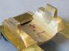
 

OzzyO

Western Thunderer
Hello all,

A good start on cutting out the curved part of the "saddle" part of the steam pipe casing, in this photo I'm down to the top of the large part of the casing. As you can see I'm getting a bit of tool chatter but I'm taking about 1mm a cut at the moment. The weight when I started this part of the operation was 158 Grams.

post-8920-0-50133000-1436351483_thumb.jpg


In this photo I'm down to approx. level with the running plate so approx. 2.5mm - 3mm to go. You can just make out the joint line between the top part and the top part of the base on the R/H side. So a bit more work today and the main part of the milling should be done.

post-8920-0-81713900-1436351487_thumb.jpg

OzzyO.
 

OzzyO

Western Thunderer
Hello all,


getting near to finishing the milling, after the last photo I ran the same cut down from the top and this was the result.

post-8920-0-34589900-1436479153_thumb.jpg


Then I got a bit heavy handed and this happened.

post-8920-0-02641800-1436479183_thumb.jpg


Trying the casing in place on the running plate. I've still got the radius corners to sort out and the mounting plate that will go under the casings.

post-8920-0-82325100-1436479187_thumb.jpg

post-8920-0-18762600-1436479194_thumb.jpg

post-8920-0-31803300-1436479198_thumb.jpg


This is when the next job shows up, the inside valve chest cover, that is too tail this looks like the D.As. did not take in to account that the front running plate is 5" higher than the rear one. I'm also going to have to fit a length of brass under the front edge of the casing.

post-8920-0-11898600-1436479204_thumb.jpg

post-8920-0-56289600-1436479208_thumb.jpg


OzzyO.
 

OzzyO

Western Thunderer
Hello all,


as some you may remember I did question Slater's about the wheels for Anne (and the Princesses class) in 7mm. I was looking through the price list for 2012 and spotted the following,

Date on the front cover,

post-8920-0-22258700-1437687896_thumb.jpg


The 7mm wheels, 7878ST, bottom of the page.
When I question Slater's about them these were correct, according to all the information that they had to work with.

post-8920-0-58766200-1437687909_thumb.jpg


I was looking for something else in the same price list and came across this page, 24/25 Larger scale wheels (it's in the section Gauge 1 (10 mm scale) locomotive wheels. Under ref. No. S9878ST. See below.

post-8920-0-08141600-1437687919_thumb.jpg


So all I can say is that Slater's do know that they are selling the wrong product to any 7mm modeller that is making a model of a Princess class loco.


OzzyO.
 

oldravendale

Western Thunderer
Maybe it's time to ask David to explain this discrepancy? I've always found him very fair - I'll talk to him at Guildex unless anyone gets to him first.

Brian
 

OzzyO

Western Thunderer
Hello all,

well after seeing how the steam pipe casing sets the smokebox position below the front valve chest casing, so it just has to come off. The first job is to cut down near the front frame extensions.
post-8920-0-79138500-1437911961_thumb.jpg

and there it is gone, still some cleaning up to be done.
post-8920-0-40066200-1437911970_thumb.jpg

I had to do a modification at the front end below the saddle part, this is to fill the gap in the running plate and the gap between the frames.
post-8920-0-40526000-1437911979_thumb.jpg

Testing the fit of the casing on the running plate and the frames.
post-8920-0-43558500-1437911987_thumb.jpg

post-8920-0-99817000-1437911995_thumb.jpg

When I fitted the mounting plate for the cylinders this is what I found. A gap at the rear of the casing that I did not want.
post-8920-0-74304400-1437912004_thumb.jpg

So I ended up having to remove approx. 1.25mm from the rear end of the 25.4mm section and also part of the front end for the fixing screw. On the side that's closest to you you can see two purple marks these are for the fixing screws (12BA), but I think that I'll only use the two front ones as the rear one's are a bit close to the angled face and could break through.
post-8920-0-78053000-1437912024_thumb.jpg

Front holes drilled and tapped. I'm still thinking about the rear two. I may drill and tap them but a bit further forward.
post-8920-0-97237600-1437912032_thumb.jpg

Some shaping of the front of the casing has been undertaken. It is only sitting up like this due to the two fixing screws being in place.
post-8920-0-28785700-1437912042_thumb.jpg

I've also been doing some work on the rods, but the uploads have failed, so I'll come back to them.

OzzyO.
 

OzzyO

Western Thunderer
Hello all,

I did get asked why I was going to all of this trouble to replace the casing casting. With a bit of luck these three photos should show why. This photo shows the outline of both of them, the green line is the casting and the red line the M/C up one. Before I fit it I'm going to have to remove a small amount from the main frames in front of it to clear the inside valve chest cover.
post-8920-0-12530200-1438072808_thumb.jpg

The casting in place, I've moved the front end in a bit to get it a bit more parallel to the running plate edge.
post-8920-0-90457000-1438072816_thumb.jpg

The M/c up one.
post-8920-0-95105400-1438072825_thumb.jpg

Go on what do you think?

OzzyO.
 
Top