Chas Levin
Western Thunderer
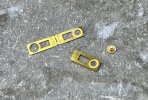
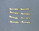
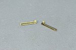
The sprung bearing carriers are a fold-up, with a neatly done half-etch pattern on what becomes the inside, partly to allow the springs through, partly to allow the bearing to sit flush with the inside of the assembly. The next photo shows two of the carriers, one before folding, where you can see the bearing seating ring and the inside generally, one after folding where you can see the 'socket' formed by the two sides, in which the bearing will sit:
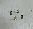
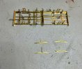
And here are the four carriers, folded up with bearings soldered in too:
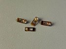
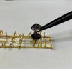
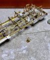
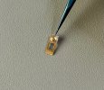
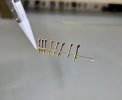
They're a nice example of the power of soldering flux (in this case phosphoric acid) to draw solder through joints and the importance of restricting the area of application of solder. The instructions emphasise that the iron and the solder must only be applied to one point, being indicated in the photo below by tweezers, otherwise it'll flow too far through the folded piece and fill the hole where the spring wire has to go and what you see in this photo - the ring of solder round the bearing etc - is the result of doing that:
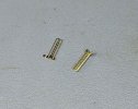
Four 17mm lengths of the spring wire are then given a 2mm bend at one end and then threaded through the top of each carrier:
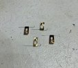
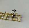
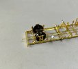
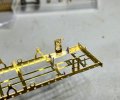
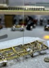
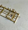
They're then put on one side for other soldering to the underframe, but I couldn't resist trying out one carrier in place, which involves some slightly fiddly fitting of the spring. Hopefully you can see the spring in these photos - it looked much more prominent in real life and doesn't seem to show up very well on screen, so I'll try and take some better photos when the carriers are fitted again, later in the build:
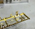
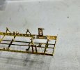
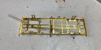
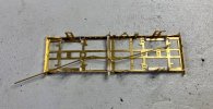
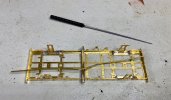
Next is the oil draw-off pipe, for which a piece of 5/64" brass pipe (a hair under 2mm) needs to be bent into a sort of flat-bottomed U-shape. I was concerned that the pipe would fold or crease and thought about bending it with a suitably sized piece of wire filling the inside but in the event, it didn't need it:
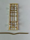
The bend is necessary to give clearance for the vac pipe and brake rodding:
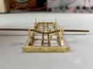
I did however have difficulty forming the fairly flat bottom to the curve and the fairly sharp shoulders to rise from that to the holes in the brackets, particularly as I made the mistake of trimming the pipe to length before getting the curve sufficent to give the needed clearance, so I had to resort to rather unscientific and slightly risky things like inserting the end of a 1.4mm drill into the pipe to give some purchase and allow a little further adjustment of the bend:
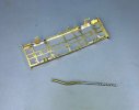
I found I could get it very close but without quite achieving clean clearance for the vac pipe:
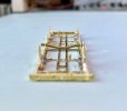
So I cheated a little, filing a small groove in the top of the draw-off pipe, to be sure the vac pipe will pass over it easily - the groove will be hiddne between the pipes of course:
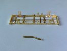
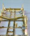
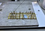
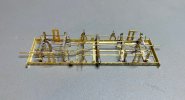
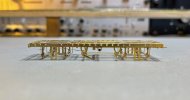
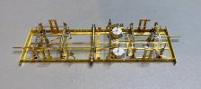
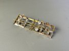
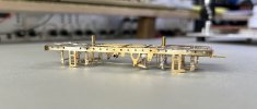
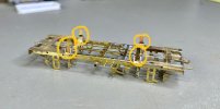
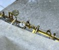
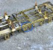
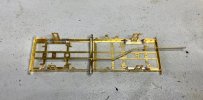
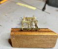
And soldered into place, with the pipe mouth circled in red on the side view:
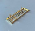
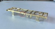
It's left deliberately long as per the instructions, to be filed down when the solebars are available for trial fitting at least, to judge the length.

And here are the four carriers, folded up with bearings soldered in too:

They're a nice example of the power of soldering flux (in this case phosphoric acid) to draw solder through joints and the importance of restricting the area of application of solder. The instructions emphasise that the iron and the solder must only be applied to one point, being indicated in the photo below by tweezers, otherwise it'll flow too far through the folded piece and fill the hole where the spring wire has to go and what you see in this photo - the ring of solder round the bearing etc - is the result of doing that:

Four 17mm lengths of the spring wire are then given a 2mm bend at one end and then threaded through the top of each carrier:

They're then put on one side for other soldering to the underframe, but I couldn't resist trying out one carrier in place, which involves some slightly fiddly fitting of the spring. Hopefully you can see the spring in these photos - it looked much more prominent in real life and doesn't seem to show up very well on screen, so I'll try and take some better photos when the carriers are fitted again, later in the build:


Next is the oil draw-off pipe, for which a piece of 5/64" brass pipe (a hair under 2mm) needs to be bent into a sort of flat-bottomed U-shape. I was concerned that the pipe would fold or crease and thought about bending it with a suitably sized piece of wire filling the inside but in the event, it didn't need it:

The bend is necessary to give clearance for the vac pipe and brake rodding:

I did however have difficulty forming the fairly flat bottom to the curve and the fairly sharp shoulders to rise from that to the holes in the brackets, particularly as I made the mistake of trimming the pipe to length before getting the curve sufficent to give the needed clearance, so I had to resort to rather unscientific and slightly risky things like inserting the end of a 1.4mm drill into the pipe to give some purchase and allow a little further adjustment of the bend:

I found I could get it very close but without quite achieving clean clearance for the vac pipe:

So I cheated a little, filing a small groove in the top of the draw-off pipe, to be sure the vac pipe will pass over it easily - the groove will be hiddne between the pipes of course:


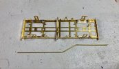
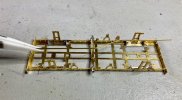
And soldered into place, with the pipe mouth circled in red on the side view:


It's left deliberately long as per the instructions, to be filed down when the solebars are available for trial fitting at least, to judge the length.

 .
.