davey4270
Western Thunderer
Work on Trojan sees the cylinder wrappers soldered on and cleaned up. A Slater’s suspension unit on the front axle has an added benefit of allowing the wheel set to be dropped out without disassembly. The cylinders have been bolted in place inline with the driven (rear) axle and the next job will be the slide bar supports. The excess of the crank pins will need to be removed before the front wheel set can rotate but, hopefully, there will be sufficient clearance between the crank pins and the cross heads. The pictures don’t show this clearly due to lens distortion. Extra clearance will be gained by reversing the crank pin bearing, placing the retaining washer under the coupling rod to space it out to match the flange of the rear bearing and securing the reversed bearing with a spot of thread lock thus doing away with the nut.
The Beatles and Lenny Kravitz helped today.
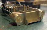
The inverted frames illustrating that the leading wheel set is easily dropped out. This also shows the front plate in its correct position. Am I glad that I hadn't got round to soldering the riveted brackets in place!
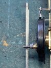
The Left hand crank pin showing, hopefully, sufficient clearance. Must get that surface fust off the wheel, a wipe with WD40 usually suffices.
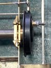
And the right hand wheel, didn't get the camera angle right this time.
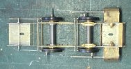
An overall view of the inverted chassis, must straighten those brake push (in this case) rods.
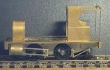
Here he/she/it is, just placed together for the camera.
The Beatles and Lenny Kravitz helped today.

The inverted frames illustrating that the leading wheel set is easily dropped out. This also shows the front plate in its correct position. Am I glad that I hadn't got round to soldering the riveted brackets in place!

The Left hand crank pin showing, hopefully, sufficient clearance. Must get that surface fust off the wheel, a wipe with WD40 usually suffices.

And the right hand wheel, didn't get the camera angle right this time.

An overall view of the inverted chassis, must straighten those brake push (in this case) rods.

Here he/she/it is, just placed together for the camera.


