7mm David Andrews Princess - 6206 Princess Marie Louise

OzzyO

Western Thunderer
Hello Rob,

some of the best fixtures are made by that company Heath, Robinson. Been going for donkeys years, but I've never found the shop. Now to have a walk around town and see if I can find the shop this week.

ATB

OzzyO.

PS. I do talk some :shit: at times.
Must go the nice men in the white coats and my new jacket with the very long sleeves have just turned up. I'll get to play in that nice room with the soft walls and floor.
 

Rob Pulham

Western Thunderer
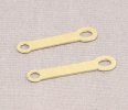
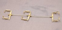
These are the drawbar options as supplied. I have a confession to make at this stage. I couldn't find them and had asked a couple of fellow modellers who have the same kit for dimensions. As it happens one was able to supply part numbers and the other the key dimensions.

Then as is often the way, I opened a box where I keep useful bits (actually looking for a piece of plug pin to see if it would be suitable to make a draw bar from) and there on top of all the bits and pieces was the square of etch containing the two missing drawbars.

53714718832_cd44eda1ef_b.jpg

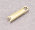
While I completely understand why they would be supplied as etches I wanted to see if I could make something more 3 dimensional.

I made a complete hash of my first attempt due to getting the machining operations in the wrong order. I had started by milling and drilling which left the part too weak when I attempted to turn the dog bone section.

53716091805_7e03bccc87_b.jpg

This was at the end of the turning operation on the second attempt.

53715997659_1df3e2ee0a_b.jpg

53715969364_e98320eb1e_b.jpg

53716064175_2bef3a39ec_b.jpg

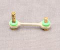
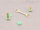
This is the end result greatly enlarged of course. The insulated bushes were made from knitting needles. sadly the only one I had of the right thickness was green. I did think that I had a suitable grey one but having turned one and subsequently dropped it, it landed with a decidedly metallic click. Further investigation revealed that it was in fact aluminium not plastic so not much cop for insulated bushes...
 

Rob Pulham

Western Thunderer
The Princess is keeping me entertained to the end.

Almost the last thing to fit are the sand pipes but in order to do that I needed to refit the brakes so that I can work out how the sand pipes will fit around them.

Previously after fitting the 3D printed shoes I had fixed the hangers to the frames via soldered pins with the top of the hanger slipping over a square rod (the holes were etched square) for mounting. Having come back to it I wasn't happy with that arrangement so I removed the pins and substituted some lengths of 12BA stud instead (cut down screws) next I soldered the square end into the hanger brackets. Then I enlarged the holes in the frames so now I can insert the studs through and put nut on the back to hold them.

A bonus to this approach is that not only will it be easier if a little fiddly to get them on and off the studs will rotate in the frames before being fully tightened so that positioning of the shoes against the wheels will be more adjustable.

53725156277_7bb4e22e51_b.jpg
 

Rob Pulham

Western Thunderer
After fitting the brakes, I have spent far too much time in the last week or so trying to fit the sand pipes. What's so difficult you might as yourself? Well they fit inside the frames and they also need to fit in such a way as to allow the wheels and brakes to be removable (the wheels won't come out unless you remove the brakes). the key issue has been getting the pipes to bend in a tight enough bend to allow them to fit without touching the next wheel along.

In the end I have started again by stripping all the pipe work off the brackets and the plan is to reinstate them with finer soft brass and copper wire. I have cut all the parts and I will share picture when I have them reassembled ready to fit.
 

Rob Pulham

Western Thunderer
Well I have the replacement sand pipes assembled ready for fitting let's hope I have more luck in fitting these. One pipe is soft brass and the other slightly thinner one is copper.

53746398329_ebe41a1bae_b.jpg

Below are the first ones that I made earlier in the build. I made myself a rod for my own back (if you will pardon the pun) by using hard brass rod for the thicker of the two pipes which when it came to it, was almost impossible to bend where I needed it to go.


53340278383_d2ef57e4a6_b.jpg
 

Rob Pulham

Western Thunderer
The sand pipes are now fitted without interfering with anything. I did get them fitted a couple of days ago but when I added the front bogie they stopped it from moving. I removed the two front ones and moved them slightly further back which did the trick.

53759850355_127ef3dc0d_b.jpg

53759768754_d313170530_b.jpg
 

OzzyO

Western Thunderer
Hello Rob, all,

if your using hard brass and you can't get it to form to the shape that you want.
Just apply heat from a gas lighter etc. until it's red hot you can quench it or just let it go cold and bingo you have soft wire in the part that you applied the heat to.

ATB

OzzyO.
 

James Spooner

Western Thunderer
The sand pipes are now fitted without interfering with anything. I did get them fitted a couple of days ago but when I added the front bogie they stopped it from moving. I removed the two front ones and moved them slightly further back which did the trick.

View attachment 216625

View attachment 216626
Hi Rob,

That is looking very good but one question from someone who isn’t very well up on ex LMS designs: should the return crank on the left hand side be so far out from the axle centre? Won’t that provide an element of movement that is far greater than that given on the right hand side? Logically that would mean the travel on the piston valves would be different for each cylinder, which doesn’t seem right to me. But, hey, I’m just an accountant so feel free to shoot me down in flames!

Nigel
 

Rob Pulham

Western Thunderer
Hi Rob,

That is looking very good but one question from someone who isn’t very well up on ex LMS designs: should the return crank on the left hand side be so far out from the axle centre? Won’t that provide an element of movement that is far greater than that given on the right hand side? Logically that would mean the travel on the piston valves would be different for each cylinder, which doesn’t seem right to me. But, hey, I’m just an accountant so feel free to shoot me down in flames!

Nigel
Hi Nigel,

Well spotted, I must have moved it out of position when I have been messing with the sand pipes. When fully tightened it should sit in the same position as the right hand side.
 

Rob Pulham

Western Thunderer
Hello Rob, all,

if your using hard brass and you can't get it to form to the shape that you want.
Just apply heat from a gas lighter etc. until it's red hot you can quench it or just let it go cold and bingo you have soft wire in the part that you applied the heat to.

ATB

OzzyO.
Hi Paul,

Had I thought of that before I assembled them, I could have softened it. But once assembled, heating them up would have made them fall to bits, so just as easy to remake with soft wire. Lesson learned!
 

spikey faz

Western Thunderer
These are the drawbar options as supplied. I have a confession to make at this stage. I couldn't find them and had asked a couple of fellow modellers who have the same kit for dimensions. As it happens one was able to supply part numbers and the other the key dimensions.

Then as is often the way, I opened a box where I keep useful bits (actually looking for a piece of plug pin to see if it would be suitable to make a draw bar from) and there on top of all the bits and pieces was the square of etch containing the two missing drawbars.

View attachment 215166

While I completely understand why they would be supplied as etches I wanted to see if I could make something more 3 dimensional.

I made a complete hash of my first attempt due to getting the machining operations in the wrong order. I had started by milling and drilling which left the part too weak when I attempted to turn the dog bone section.

View attachment 215167

This was at the end of the turning operation on the second attempt.

View attachment 215168

View attachment 215169

View attachment 215170

This is the end result greatly enlarged of course. The insulated bushes were made from knitting needles. sadly the only one I had of the right thickness was green. I did think that I had a suitable grey one but having turned one and subsequently dropped it, it landed with a decidedly metallic click. Further investigation revealed that it was in fact aluminium not plastic so not much cop for insulated bushes...
Hi Rob

Would something like this do the job?
20240604_092944.jpg20240604_092954.jpg

Mike
 

Rob Pulham

Western Thunderer
Hi Mike,

It's a nice idea but sadly they are too big for this application. The thickness of the draw bar and the flats at either end is 2mm so while the threaded element at M2 might work the rest would be too big. Thanks for the suggestion though as I might find a use for them in the future.

Regards Rob
 

Rob Pulham

Western Thunderer
Returning briefly to post #529 where Nigel pointed out that the return crank had moved. This came back to bite me.

Initially I just thought that in lifting the loco up I had dislodged it causing it to unscrew and come loose. However no matter how much I tried I couldn't get it to tighten back up in the right place. I tried shortening the bush but realised too late that the crank pin itself must have shifted in the wheel. Then having shortened it I found that when tight it was nipping the conrod and coupling rods so that they wouldn't move.


Making a replacement bush was the order of the day.

IMG_0001.jpgReplacement return crank bush
 

adrian

Flying Squad
Initially I just thought that in lifting the loco up I had dislodged it causing it to unscrew and come loose. However no matter how much I tried I couldn't get it to tighten back up in the right place. I tried shortening the bush but realised too late that the crank pin itself must have shifted in the wheel. Then having shortened it I found that when tight it was nipping the conrod and coupling rods so that they wouldn't move.
I've built a few loco's and used a similar method for fixing the return crank. Also found similar problems w.r.t. position shifting. From an engineering point of view it just doesn't work correctly for me. At some point I need to work out a better solution but never found a suitable one yet.
 

Ian@StEnochs

Western Thunderer
Rob,

Crankpin screws moving gave me a problem too when I built my Scot. I solved it by locking the screw with a little U shaped 0.5 brass wire staple melted into the slot and wheel effectively preventing the screw from turning. That works for Slaters wheels.
The AGH wheels you are using are different though usually the crankpins is pressed into an insulating tufnol bush. Refitting with Locktight or similar may be your best bet.

Ian.
 

spikey faz

Western Thunderer
I've built a few loco's and used a similar method for fixing the return crank. Also found similar problems w.r.t. position shifting. From an engineering point of view it just doesn't work correctly for me. At some point I need to work out a better solution but never found a suitable one yet.
Maybe something like this would work:

Markits

Mike
 
Top