You are using an out of date browser. It may not display this or other websites correctly.
You should upgrade or use an alternative browser.
You should upgrade or use an alternative browser.
Easton Mill
- Thread starter Easterner
- Start date
oldravendale
Western Thunderer
Josh - that photo of 44871 and Mayflower. Is it at Southall? I ask as it was a favourite stomping ground of mine up to the demise of seam and I've never been back!
Brian
Brian
Easterner
Western Thunderer
Thanks for all your kind words.
Brian, yes that is at Southall just poking out the front of the shed!
In regards to the indexed sector plate. It's been a bit of a long winded affair and a fairly sizeable stumbling point up until recently as I'm a big believer of making sure everything is wired and runs correctly before progressing with scenery, something drummed into be from a young age!
I indexed and motorised it because back when I started "Easton Mill" I was still living at home, the layout sat in a "culvert" in my bedroom so there was no real way of accessing the rear of the layout, now I've got my own place and it's set up in the spare/model room it's not so much of an issue.
I originally set about designing it with the help of a chap named Dave Instone who was well involved with Arduino and MERG. Between us we came up with a list of parts and things to get the ball rolling, however due to work and other interests at the time the layout went on the back burner as these things do from time to time and by the time I got back into in the early part of 2021 Dave had sadly passed away.
I'm not a great under-stander of Arduino and how it all works, so this left me in a bit of a tight spot. Luckily I stumbled across a thread on RMweb, by Tender (Ray) who was trying/had achieved a similar sort of mechanism: A New Year, a New Layout - 7mm+ modelling - RMweb which I think had come from another thread which focused more on turntables: DCC Controlled (PECO) Turntable Project using a Arduino Uno - Page 28 - DCC Discussion Topics (not questions) - RMweb
After a few discussions with Ray, he pointed me in the direction of Ian @ DCC Interface and one of his turntable/traverser accessory decoders:
Model Railway DCC Turntable/Traverse Accessory Decoder with TMC2208 - Assembled | DCC Interfaces
Ian was initially very helpful, quickly dispatched the decoder and got me off the ground with the project again, however as time went on he struggled to help me with the program/software I required to make my sector plate work. Fast forward a bit and after a few more rather in depth conversations with Tender (Ray), he designed and sent me a program which after several tweaks is now what I'm running on the DCC Interface Decoder.
I can move the traverser using Macros on the NCE Powercab (Essentially like driving point motors) or I can activate the position required from the 3 push buttons on the control panel which you should be able to make out from my last posting, this required a slight modification/addition the the standard DCC interface board.
So in a nut shell, the main drive is from one of these:
100mm Long Stage Actuator Linear Stage 1204 Ball Screw Linear Slide Stroke With 42mm Stepper Motor
There is a nut an bolt assembly that passes through the end of the sector plate which connects the sector plate to the ball screw slide assembly. On the main drive block there is some bent and shaped aluminium which forms a guide for the nut and bolt assembly to pass through and also activates a micro-switch which is mounted to the bottom of the ball screw slide assembly. In the initial design I was going to use a micro-switch for each position, however there is now only one micro-switch on the slide assembly which lines up with the loop road (Position 1). When powered up, the sector plate moves at half speed until it activates the micro-switch which acts as the datum point for the software. From this, the required steps for the stepper motor that drives the assembly are then programmed into the Arduino Nano via. the Arduino software which is mounted on/forms part of the DCC Interface Decorder. This forms three positions within the software which are then actioned when you push the associated push buttons or accessory number on the Powercab.
Hope this explains things.....If you want to know anymore please let me know.
A diagram and few pictures which will also hopefully aide to my description above!


cbrailways
Western Thunderer
Hi Josh. Thanks for that very detailed explanation and photographs. Time do do some research using the links you provided.
Easterner
Western Thunderer
Today it's been a primering sort of day!
It's slowly becoming apparent how easy it is to just pick up a wagon kit and why nothing gets done on the layout.
I dare mention that this is only a 3rd of them that are awaiting finishing - Hopefully I'll end 2021 & start 2022 by clearing the backlog before I start anything else....

It's slowly becoming apparent how easy it is to just pick up a wagon kit and why nothing gets done on the layout.
I dare mention that this is only a 3rd of them that are awaiting finishing - Hopefully I'll end 2021 & start 2022 by clearing the backlog before I start anything else....


Simon
Flying Squad
They all look very nice, the gunpowder van is an especially nice shape and something I would really like to make in 1/32, but there are rather a lot of other projects on the go. Your completed Toad E with the steel ducket is also especially handsome and mine isn't too far behind yours.
As far as your comments go, I don't think that anyone can ever have too many wagons!!
Simon
As far as your comments go, I don't think that anyone can ever have too many wagons!!
Simon
AJC
Western Thunderer
I was only thinking the other day that perhaps I don't have enough...
Going back to the above photo featuring the gunpowder van, can I ask Josh, what is the middle van of the three?
Rob.
Looks GER to me? The idea of an upper limit of wagon numbers seems like some kind of mental aberration. Too many locos, on the other hand…
Adam
Easterner
Western Thunderer
Afternoon All.
Apologies for the typical lack of updates, there has been some progress but there's been a few other distractions again.
A fair chunk of modelling time has been taken up experimenting with DCC Sound Speakers in Heljan Diesels. A friend asked me to upgrade his Loksound 3.5 sound chip to a Zimo decoder with Paul Chetters latest sound files, which led me onto fitting sound to my own Class 47. Both now complete, the 47 now awaits a crew, numbering and weathering.
Some time was also spent helping another couple of friends with a small 0 Gauge Diesel Depot to get it ready for a local exhibition, this included some minor wiring modifications, fitting lights and general help.
Aside from that, I've been trying to decide what to do with backscene so to progress things it has all been given several coats of some white cieling paint I had left over which has certainly brightened up the layout. In addition to this I've also finished painting rails a dark rust colour, plastered the front scenery and given it a coat of brown, along with a dull blue for what will become the pond. The next job I think will be moving onto ballasting, followed by finalising the rest of the scenery at the rear of the layout.
Anyway, some pictures of progress and other musings!
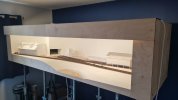

The above photos show the initial change from giving the backscene a coat of paint.

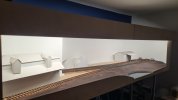
Followed by progress on the landscaping.
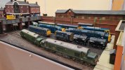
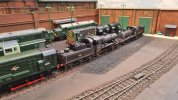
The small Diesel MPD I've been assisting with, even managed to sneak a couple of steam locos in!
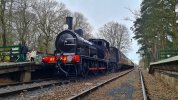
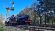
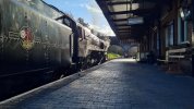
And the continued distraction of voluntary driving turns at the North Norfolk Railway.
Apologies for the typical lack of updates, there has been some progress but there's been a few other distractions again.
A fair chunk of modelling time has been taken up experimenting with DCC Sound Speakers in Heljan Diesels. A friend asked me to upgrade his Loksound 3.5 sound chip to a Zimo decoder with Paul Chetters latest sound files, which led me onto fitting sound to my own Class 47. Both now complete, the 47 now awaits a crew, numbering and weathering.
Some time was also spent helping another couple of friends with a small 0 Gauge Diesel Depot to get it ready for a local exhibition, this included some minor wiring modifications, fitting lights and general help.
Aside from that, I've been trying to decide what to do with backscene so to progress things it has all been given several coats of some white cieling paint I had left over which has certainly brightened up the layout. In addition to this I've also finished painting rails a dark rust colour, plastered the front scenery and given it a coat of brown, along with a dull blue for what will become the pond. The next job I think will be moving onto ballasting, followed by finalising the rest of the scenery at the rear of the layout.
Anyway, some pictures of progress and other musings!


The above photos show the initial change from giving the backscene a coat of paint.


Followed by progress on the landscaping.


The small Diesel MPD I've been assisting with, even managed to sneak a couple of steam locos in!


And the continued distraction of voluntary driving turns at the North Norfolk Railway.
Joe's Garage
Western Thunderer
Hi Josh, lovely to see the J15 (Y14) back in GE livery. I saw it back in about 1985!
Very nice layout by the way...
All the best
Julian
Very nice layout by the way...
All the best
Julian
Joe's Garage
Western Thunderer
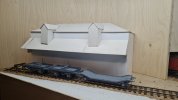
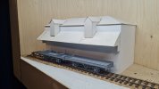
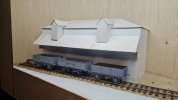
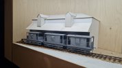
Nice progress with the layout also Josh, which mill did you decide in the end or is it just a card mock up? It got me thinking about some of the mills around Hertford, particularly Hertingfordbury Mill. (Now converted into residential accommodation!)
I have attached a couple of photos from the Internet so usual copyright disclaimers etc. Lovely yellow brick. I remember it from the late 1980s when I lived in Hoddesdon.
Keep posting
All the best Julian
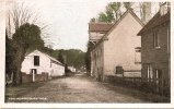
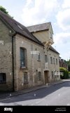
I have attached a couple of photos from the Internet so usual copyright disclaimers etc. Lovely yellow brick. I remember it from the late 1980s when I lived in Hoddesdon.
Keep posting
All the best Julian


 .
.


