You are using an out of date browser. It may not display this or other websites correctly.
You should upgrade or use an alternative browser.
You should upgrade or use an alternative browser.
The chassis has now been sprayed.

It looks a little less glossy in the flesh than it does in this photo.
There were a few head scratching moments working out how best to fit the cab floor and bunker front into place. in the end I made the floor sub-assembly and soldered it in place on the bunker front and slid this into position. It was very tight until the coal chute located and everything relaxed.

The footplate was bent to shape and the splashers added. The fitting of these has been well thought out. I also did the front end but am not totally pleased with it.

Underneath I made up the step assemblies, and added them, the injector supports and buffer beam strengthening plates.

At the rear the handrails, lampirons buffer beam overlay and coupling hook strengthening plate.


I am not too happy with the front end. I had a few problems with the assembly. There are three overlays that fit on the front end former. All of them suffered form the slots for the lamp irons being too small. The lamp irons are part of the former. I have not been able yet to get the three pieces to form a nice straight line above the buffer beam but I'll keep fettling. I think an issue here is how the bends in the former are formed. there is enough tolerance in the fold lines to make a small difference in the folded up size of the former. I ran into an issue with the side overlays being a bit small, but perhaps it's OK.

You can see the joins in front of the frame extensions. I have yet to add the hinge and knob detail to the inspection covers and there is an overlay to add for the buffer beam.
It looks a little less glossy in the flesh than it does in this photo.
There were a few head scratching moments working out how best to fit the cab floor and bunker front into place. in the end I made the floor sub-assembly and soldered it in place on the bunker front and slid this into position. It was very tight until the coal chute located and everything relaxed.
The footplate was bent to shape and the splashers added. The fitting of these has been well thought out. I also did the front end but am not totally pleased with it.
Underneath I made up the step assemblies, and added them, the injector supports and buffer beam strengthening plates.
At the rear the handrails, lampirons buffer beam overlay and coupling hook strengthening plate.
I am not too happy with the front end. I had a few problems with the assembly. There are three overlays that fit on the front end former. All of them suffered form the slots for the lamp irons being too small. The lamp irons are part of the former. I have not been able yet to get the three pieces to form a nice straight line above the buffer beam but I'll keep fettling. I think an issue here is how the bends in the former are formed. there is enough tolerance in the fold lines to make a small difference in the folded up size of the former. I ran into an issue with the side overlays being a bit small, but perhaps it's OK.
You can see the joins in front of the frame extensions. I have yet to add the hinge and knob detail to the inspection covers and there is an overlay to add for the buffer beam.


It has been far too long since I posted any updates here, but reading the W1 thread and the comments about Piercy kits spurred me into showing some photos of my latest build - the Piercy/DJH B1, now nearing completion. So just a few photos with points of interest as it were!

No problems in building the bogie. This has a nice side control mechanism with lateral springing of the bogie pivot post.
The chassis builds well as a rigid unit. I made the cylinders removable by soldering an M2 screw to the backing plate and using this and the two locating lugs to fix it to the frames rather than soldering the backing plates to the frames and then adding the cylinders.

The kit features a working screw reverser, seen here before adding the cover plate.

This enables you to set the loco in any gear form reverse to forward.


Smokebox interior details are provided.

And an opening door to see them!

I modified the doors by adding a length of tube to act as a hinge pin for 0.5mm brass hinge.


The most troublesome part of the kit by far is the smokebox saddle. This doesn't fit at all well and requires the frames to be cut out to take it.

And replacement frame extensions made. I did these out of scrap nickel silver, seen here with a white metal original.

Here seen fitted in place.

When building the tender I would recommend ignoring the advice to use super glue to fit the tank top rear into the etched rebate in the sides as it isn't string enough. It would have been better to make a support for the top out of brass section. The modification I did make was to drill out the frame rivets for the cross members rather than embossing the rivets and to use brass rivets instead. Two of these per side per member are used to hold the stretcher in place and kept unglued as it makes it possible then to dissassemble the tender bogie from the body.

Here the tender is complete bar the door locks that have since been added.

She should be finished tomorrow, so more pictures then.
No problems in building the bogie. This has a nice side control mechanism with lateral springing of the bogie pivot post.
The chassis builds well as a rigid unit. I made the cylinders removable by soldering an M2 screw to the backing plate and using this and the two locating lugs to fix it to the frames rather than soldering the backing plates to the frames and then adding the cylinders.
The kit features a working screw reverser, seen here before adding the cover plate.
This enables you to set the loco in any gear form reverse to forward.
Smokebox interior details are provided.
And an opening door to see them!
I modified the doors by adding a length of tube to act as a hinge pin for 0.5mm brass hinge.
The most troublesome part of the kit by far is the smokebox saddle. This doesn't fit at all well and requires the frames to be cut out to take it.
And replacement frame extensions made. I did these out of scrap nickel silver, seen here with a white metal original.
Here seen fitted in place.
When building the tender I would recommend ignoring the advice to use super glue to fit the tank top rear into the etched rebate in the sides as it isn't string enough. It would have been better to make a support for the top out of brass section. The modification I did make was to drill out the frame rivets for the cross members rather than embossing the rivets and to use brass rivets instead. Two of these per side per member are used to hold the stretcher in place and kept unglued as it makes it possible then to dissassemble the tender bogie from the body.
Here the tender is complete bar the door locks that have since been added.
She should be finished tomorrow, so more pictures then.


Dibatag is now with Warren for painting, so I have made a start on the next job: a David Andrews A3, Hyperion.
This will be fitted with a set of Premier Components rods, so no need to laminate coupling rods as the first job. I have remembered to cut out the glazing though. Always easier when the etches are still on the frets.
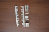
First part of the construction has been the tender chassis. This is supplied as nice thick nickel silver etches.

These fitted together very well.


the two inner axles will float so the holes for the bearings have been enlarged to follow the profile of the half-etched section. The bearings for these were drilled 0.7mm to take a nickel silver wire that fits through a spacer above the axle that will also contain the 6BA screw that will act as the centre pivot about which the axles can rock.

the instructions suggest fitting 0.9mm wire to act as the brake hanger supports, but I have used some tube with 0.5mm ID into which lengths of 0.5mm nickel silver wire soldered to the brake hangers can be fitted. This allows the brake rigging to be removed at a later date. With the pull rods being either side of the wheels, wheel removal would otherwise be difficult.
The pull rods and other brake linkages were added. the brake beam on the leading axle is not fitted to the brake hangars so the rodding is removable.


At this point I realised that the vacuum brake reservoir needed to be fitted before the rear brake hangar tube was fitted. The casting includes holes for the rod to go through, but no good if the rod is already soldered in place! I'll slot the supports instead. So just this and the water scoop to add and the tender bogie will be ready for painting.
This will be fitted with a set of Premier Components rods, so no need to laminate coupling rods as the first job. I have remembered to cut out the glazing though. Always easier when the etches are still on the frets.
First part of the construction has been the tender chassis. This is supplied as nice thick nickel silver etches.
These fitted together very well.
the two inner axles will float so the holes for the bearings have been enlarged to follow the profile of the half-etched section. The bearings for these were drilled 0.7mm to take a nickel silver wire that fits through a spacer above the axle that will also contain the 6BA screw that will act as the centre pivot about which the axles can rock.
the instructions suggest fitting 0.9mm wire to act as the brake hanger supports, but I have used some tube with 0.5mm ID into which lengths of 0.5mm nickel silver wire soldered to the brake hangers can be fitted. This allows the brake rigging to be removed at a later date. With the pull rods being either side of the wheels, wheel removal would otherwise be difficult.
The pull rods and other brake linkages were added. the brake beam on the leading axle is not fitted to the brake hangars so the rodding is removable.
At this point I realised that the vacuum brake reservoir needed to be fitted before the rear brake hangar tube was fitted. The casting includes holes for the rod to go through, but no good if the rod is already soldered in place! I'll slot the supports instead. So just this and the water scoop to add and the tender bogie will be ready for painting.
Attachments
Wheels were removed and the scoop and vac res (with slotted supports) added.

Then the tender bogie re-assembled. I was going to paint it first but decided to wait until some black etch primer that I have ordered arrives. At least I know that it goes back together!


Then it was on to the tender body. Clean up the base and the one piece sides and back and fold the latter to fit in the tabs in the base. The rear of the body has useful half etched lines to locate the bend but this isn't possible at the front so there is a bit of guess work in getting the bend in the right place. The instructions suggest adding the handrail knobs now so I did that and the rear steps and rivet detail. I still need to add the lamp irons before access to the inside of the body becomes impossible.


I wish my RSU wasn't 6000 miles away............
Then the tender bogie re-assembled. I was going to paint it first but decided to wait until some black etch primer that I have ordered arrives. At least I know that it goes back together!
Then it was on to the tender body. Clean up the base and the one piece sides and back and fold the latter to fit in the tabs in the base. The rear of the body has useful half etched lines to locate the bend but this isn't possible at the front so there is a bit of guess work in getting the bend in the right place. The instructions suggest adding the handrail knobs now so I did that and the rear steps and rivet detail. I still need to add the lamp irons before access to the inside of the body becomes impossible.
I wish my RSU wasn't 6000 miles away............
Lamp irons now fitted. I had embossed the three rivets on the support bracket, but changed my mind and drilled one out and replaced it with a 0.4mm brass rivet which was then fed through the hole in the tender rear. Now needs cleaning up.

I also tacked the tank supports in place. The rear one needs a spot of adjustment which I will do when I get my big boy iron out and make the join properly. I used 145 degree solder for these to avoid disturbing the side-base joints.

I also tacked the tank supports in place. The rear one needs a spot of adjustment which I will do when I get my big boy iron out and make the join properly. I used 145 degree solder for these to avoid disturbing the side-base joints.
The BR front plate was selected and the flange and detailing strip added to the rear.

This was fitted, followed by the tank top.

The sides to the coal space were added. There is a bit of a gap at the bottom. this will be filled by scrap etch (or coal!). The flanges for the tank filler and overflow assembly were added.

Next job was fitting the flares/coal rails/beading. These are provided as a single piece. I thought about trying to form the flares before fitting, but in the end opted to fit the piece first. I started by soldering the front vertical beading strips in place and then the flare/coal rail on that side. I then formed the two bends at the rear so that the vertical beading on the other side could be fitted. I did that and then worked back until only the rear flare required fixing. At this stage it is several mm from the tank rear. Forming the flares on each side brings it forward, and forming the rear flare then puts the rear flare in the correct place. Finally the fingers in the corners were bent to shape and the corners formed with solder.


The instructions say to fit the coal rail backing plates next, but I thought it would be better to fit the division plate first. To do this you need first to construct the overflow assembly. This is formed form two pieces of brass (sides and bottom) and top. The top has to be rolled to shape and the soldered to the other piece and then cleaned up. This was a surprisingly long job, making me wish that a casting had been supplied instead! The division plate is formed by sweating together two etches.

It doesn't look like much progress since the last post, but it took several hours to do this.
This was fitted, followed by the tank top.
The sides to the coal space were added. There is a bit of a gap at the bottom. this will be filled by scrap etch (or coal!). The flanges for the tank filler and overflow assembly were added.
Next job was fitting the flares/coal rails/beading. These are provided as a single piece. I thought about trying to form the flares before fitting, but in the end opted to fit the piece first. I started by soldering the front vertical beading strips in place and then the flare/coal rail on that side. I then formed the two bends at the rear so that the vertical beading on the other side could be fitted. I did that and then worked back until only the rear flare required fixing. At this stage it is several mm from the tank rear. Forming the flares on each side brings it forward, and forming the rear flare then puts the rear flare in the correct place. Finally the fingers in the corners were bent to shape and the corners formed with solder.
The instructions say to fit the coal rail backing plates next, but I thought it would be better to fit the division plate first. To do this you need first to construct the overflow assembly. This is formed form two pieces of brass (sides and bottom) and top. The top has to be rolled to shape and the soldered to the other piece and then cleaned up. This was a surprisingly long job, making me wish that a casting had been supplied instead! The division plate is formed by sweating together two etches.
It doesn't look like much progress since the last post, but it took several hours to do this.
Len Cattley
Western Thunderer
I can't see your photo's on my Samsung phone, perhaps Adrian can sort it out.
Len
Len
adrian
Flying Squad
Sorry I'm not too sure if I can do anything. The photo's look fine to me (Safari browser on a Macbook Air) and I can't see any error messages in the admin area. If anyone else if struggling then I can dig around a bit more if required.I can't see your photo's on my Samsung phone, perhaps Adrian can sort it out.
daifly
Western Thunderer
No problems on my iPhone, iPad or Macbook Pro. I think the answer might lie closer to home, Len.I can't see your photo's on my Samsung phone, perhaps Adrian can sort it out.
Len
Len Cattley
Western Thunderer
I don't know why I can't see the photos I can see everybody's else's post's and I can see them on my ipad, it's just my Samsung Galaxy 5 I have problems.
Len
Len
Yorkshire Dave
Western Thunderer
but it took several hours to do this.
It's always the way. What appears relatively simple is usually more difficult it is to execute.
Steph Dale
Western Thunderer
Len,
I've got no problems seeing the images on my G5...
Steph
I've got no problems seeing the images on my G5...
Steph
Len Cattley
Western Thunderer
I had to open them to see them, I don't know why this phone wouldn't open them.
Len
Len
mickoo
Western Thunderer
Len the problem is that you need to update your phone, you need to download the unobtainium.dxf file, then everything will be fine 
Genghis, nice looking B1, having been 'real' up close and personal with the inside a few weeks back, they're more complex inside than many imagine, I hear that the DJH B1 and B17 are withdrawn permanently from sale as the white metal moulds are life expired.
Nice to see another DA A3 on the go, I ripped through all my stays and stretchers and built new ones that looked more prototypical, not required or necessary as the kit ones suffice well enough, just did it coz I like A3's.
The rest (so far) has gone together very well, except the smoke box saddle which is not quite right and is the current stalling point as I need to fabricate a replacement, as well as being distracted by other projects")
Mick D
Genghis, nice looking B1, having been 'real' up close and personal with the inside a few weeks back, they're more complex inside than many imagine, I hear that the DJH B1 and B17 are withdrawn permanently from sale as the white metal moulds are life expired.
Nice to see another DA A3 on the go, I ripped through all my stays and stretchers and built new ones that looked more prototypical, not required or necessary as the kit ones suffice well enough, just did it coz I like A3's.
The rest (so far) has gone together very well, except the smoke box saddle which is not quite right and is the current stalling point as I need to fabricate a replacement, as well as being distracted by other projects
Mick D
Mick: thanks for your kind comments on the B1. I did one a couple of years ago as my first ever 0 gauge kit and it took me nearly 2 years to complete! I managed this one in 3 months, including a one month break! It is now with Warren for painting and I look forward to seeing it completed.
Now it is confession time. I made a total drop off by flaring the tender sides at the top. In my defence I will cite that I was following a rear view drawing that implies that the sides were flared, though I now realise that this is confined to the transition to the rear, which is flared. Anyway I have managed to straighten it. I also found and bought some nice images from the RCTS download service. These have convinced me that the supplied beading and coal rails leave a lot to be desired. They are flat. David's instructions note that the appearance can be improved by rounding off, but my current thinking is that I will cut off the coal rails to use as a jig for replacements formed from half-round wire and have just ordered several metres to be picked up when I am home from Bangkok next week. I'll also replace the beading on the tender verticals and sides, but the jury is out as to whether or not this will require grinding back the flat section or if I can get away with soldering the half round on top. My expectation is that I will have to grind it back.


Now it is confession time. I made a total drop off by flaring the tender sides at the top. In my defence I will cite that I was following a rear view drawing that implies that the sides were flared, though I now realise that this is confined to the transition to the rear, which is flared. Anyway I have managed to straighten it. I also found and bought some nice images from the RCTS download service. These have convinced me that the supplied beading and coal rails leave a lot to be desired. They are flat. David's instructions note that the appearance can be improved by rounding off, but my current thinking is that I will cut off the coal rails to use as a jig for replacements formed from half-round wire and have just ordered several metres to be picked up when I am home from Bangkok next week. I'll also replace the beading on the tender verticals and sides, but the jury is out as to whether or not this will require grinding back the flat section or if I can get away with soldering the half round on top. My expectation is that I will have to grind it back.
mickoo
Western Thunderer
The beading appears to be more of an oval shape on the tender and coal rails.

More importantly where the beading is attached to the tender side at the front, it is also on the inside so is in fact full form, but attached as two halves. The same applies to the A3 cab side sheet, it should be beaded inside and out, something I didn't do on my DA A3 and since regret as the edge looks a bit thin, but being as the cab is all made up now there is no easy way to form and get the inside beading in. My mistake was looking at photos of Flying Scotsmans cab during refurbishment, at some point they removed the internal beading from above the cab seat area up to the cab roof part, this now appears to have been corrected on the latest rebuild.
The beading on the A3 cab looks to be true half round, but the beading on the tender appears to be a more oval cross section.
This is a section of the W1 cab, I think the A3 beading might be a touch smaller (2-½") and the GA does not give the thickness, just the width.

A section of the GNR tender showing the corner turn in and beading inside and out.

Again, no information given on size but the oval shape is represented, but probably not accurately. However the turn in is given a radius of 8".
Take care when you get to your engine frames, Hyperion is from Lot 331 and as such has no lightening holes in the frames aft of the cylinder block, but they did have a circular hole ahead of the cylinder block of 12" dia. I can't remember if the DA instructions were that specific with regards to the frame holes.
These frames (front ends) were later fitted to other engines (cut and shut between the intermediate and rear driver) when the originals cracked, there were other variations in between and I've not yet managed to track down all the variations fitted to all locos in their lives, some having two frame rebuilds in their lives. Lot 331 is the easiest to model frame wise, as they only had this type of frame for their whole lives.
Depending on your modeling date she also carried two boilers, a 94HP (10/58 - 7/60 and a 94A (6/50 - 10/58 and later 7/60 - 12/63), the HP had the round dome, the A the streamlined dome.....not banjo, that's a much smaller affair carried much earlier in their lives for a short time.
Mick D
More importantly where the beading is attached to the tender side at the front, it is also on the inside so is in fact full form, but attached as two halves. The same applies to the A3 cab side sheet, it should be beaded inside and out, something I didn't do on my DA A3 and since regret as the edge looks a bit thin, but being as the cab is all made up now there is no easy way to form and get the inside beading in. My mistake was looking at photos of Flying Scotsmans cab during refurbishment, at some point they removed the internal beading from above the cab seat area up to the cab roof part, this now appears to have been corrected on the latest rebuild.
The beading on the A3 cab looks to be true half round, but the beading on the tender appears to be a more oval cross section.
This is a section of the W1 cab, I think the A3 beading might be a touch smaller (2-½") and the GA does not give the thickness, just the width.
A section of the GNR tender showing the corner turn in and beading inside and out.
Again, no information given on size but the oval shape is represented, but probably not accurately. However the turn in is given a radius of 8".
Take care when you get to your engine frames, Hyperion is from Lot 331 and as such has no lightening holes in the frames aft of the cylinder block, but they did have a circular hole ahead of the cylinder block of 12" dia. I can't remember if the DA instructions were that specific with regards to the frame holes.
These frames (front ends) were later fitted to other engines (cut and shut between the intermediate and rear driver) when the originals cracked, there were other variations in between and I've not yet managed to track down all the variations fitted to all locos in their lives, some having two frame rebuilds in their lives. Lot 331 is the easiest to model frame wise, as they only had this type of frame for their whole lives.
Depending on your modeling date she also carried two boilers, a 94HP (10/58 - 7/60 and a 94A (6/50 - 10/58 and later 7/60 - 12/63), the HP had the round dome, the A the streamlined dome.....not banjo, that's a much smaller affair carried much earlier in their lives for a short time.
Mick D
Last edited: