Hayfields 7mm 3D Printed Turnouts

Hayfield1

Western Thunderer
423.jpeg

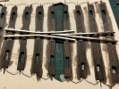
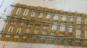
The build starts with me fitting the slide chairs and accidently the PL1 & PL2 chairs

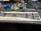
I will build the turnout in 3 subsections as I have neither half chairs or loose jaw chairs, but the FDM chairs have a little more give than the resin chairs which can be a bit brittle

424.jpeg

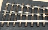
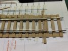
As the rails were prepared in advance the common crossing went together very well, no gauges needed due to the accuracy of the design and close fit of the parts

425.jpeg

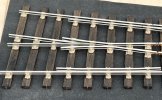
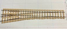
The second sub assembly (stock, check and switch rails) also was quite straight forward. I am again enjoying this build the kit is very well made and not having to cut the chairs from the supports (they just peal off the print base. Never thought I would get so much done tonight

John
 

martin_wynne

Western Thunderer
Never thought I would get so much done tonight
@Hayfield1

Hi John,

Can you do a bit of a recap?

Why are you building GOG-F instead of 0-MF?

Which version of Templot did you use to laser-cut the base?

Which version of Templot did you use for the FDM chairs? How well do they fit? Are you gluing them in, or just push fit? Are they tight enough or too tight? Did you need to fettle the sockets in order to get the 8-sided crossing chairs to sit nicely? Assuming you are using the new 8-sided chairs?

Different versions of Templot produce different results. What changes if any did you make to the Templot default settings?

How did you assemble the knuckle bends into the crossing chairs? With rails in fresh air, or with the chairs in the place in the base?

Were the rails filed in the Templot filing jigs? Are they code 125 or code 131? Did you use any superglue/epoxy on the vee rails?

Sorry to ask so many questions, but please can you provide a bit more raw detail on these builds? Thanks.

cheers,

Martin.
 

Hayfield1

Western Thunderer
Martin

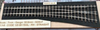
I am using one of Terry's Kosmik 3mm ply 3mm laser cut bases, you need to as terry about laser cutting, me I can just about handle a modelling knife

GOGA fine gauge

Standard Templot files used for chairs, latest version Templot 2 & 5, No changes to default settings, standard 3D builder Cura 5.6 for chairs

As for the knuckle bends, a 40 year old set of 4" plyers to pre bend the rails. The vee and wing rails were a doddle
1 First vee rail slid in place through A, B, C, L1 and S1J chairs, chairs were in fret
2 Second vee rail followed
3 The X chair was placed in the fret and first wing rail slid through the chairs
4 the second wing rail was slid though
5 I carefully eased the common crossing up at the foot end and slid on the L1 and S1J chairs and carefully pushed the crossing back in the slots

This sounds so difficult and clunky, but in affect it was so easy providing care is taken

The stock and switch rails proved just as easy, I started at the foot end and slid the chairs in place up to the check chairs leaving them in line with their slots.
I then slid the 5 check rail chairs on to the stock rail , keeping them at the end whilst I threaded on the check rail, then pushed the check rail unit in place, followed by the remaining chairs
The switch rail was fitted with chairs from the L1 chair to the S1J chair, I then slid the switch rail (with all the chairs on) which to my amazement slid through the PL3 & Pl4 chairs very easily
All the chairs were finally lined up over their slots and pushed home

It sounds far worse and complicated than it was, the FDM chairs do have a little give

As you say all chairs (other than the P chairs in the air, each one in turn was eased into place and gently eased into their slots, once all the chairs were in the slots a final push with a small wooden block firmly in place

Code 125 rail all filed up in Templot Vee and switch rail filing jigs, a spot of superglue to hold Vee and wing rails (on 1 chair only)

Sorry about not much raw details but I thought keeping it short and simple. I will take photos later of the other stock, check and switch rails and chairs. If in doubt give me a call

John
 

martin_wynne

Western Thunderer
@Hayfield1

Hi John,

Thanks for the detailed reply. It does raise quite a few questions:

GOGA fine gauge

Is Terry pushing the GOG-F standard? Nowadays most 7mm track builders use 0-MF for much improved running with modern "industry-standard" (Slaters-type) wheels. The GOG-F standard is only for the wider older-type turned cast wheels.

Is Terry providing the kits with resin or FDM chairs, or both?


The stock and switch rails proved just as easy, I started at the foot end and slid the chairs in place up to the check chairs leaving them in line with their slots.
I then slid the 5 check rail chairs on to the stock rail , keeping them at the end whilst I threaded on the check rail, then pushed the check rail unit in place, followed by the remaining chairs
The switch rail was fitted with chairs from the L1 chair to the S1J chair, I then slid the switch rail (with all the chairs on) which to my amazement slid through the PL3 & Pl4 chairs very easily
All the chairs were finally lined up over their slots and pushed home

I suggest fitting the check rails before the stock rails. Slide the check chairs onto the check rail, and push them all down into place. Make sure to get the check chairs the right way round -- the rail seat is narrower on the check rail side.

You can then pre-fit all the other stock rail chairs, and then slide in the stock rail in the same way as for COT track.

The same for the switch rails -- pre-fit all the chairs and slide them in from the toe end, the same as for COT.


As for the knuckle bends, a 40 year old set of 4" plyers to pre bend the rails. The vee and wing rails were a doddle
1 First vee rail slid in place through A, B, C, L1 and S1J chairs, chairs were in fret
2 Second vee rail followed
3 The X chair was placed in the fret and first wing rail slid through the chairs
4 the second wing rail was slid though
5 I carefully eased the common crossing up at the foot end and slid on the L1 and S1J chairs and carefully pushed the crossing back in the slots

This sounds so difficult and clunky, but in affect it was so easy providing care is taken

This raises a few issues which I might need to deal with.

The default FDM plugs are the snap-fit type with tangs/barbs on the side of the plug intended to be fitted once only. If you ease them out from the plywood and re-fit them they are likely to become loose and need gluing, and you might lose some track-gauge accuracy in the process. This could be important in P4 or S7.

There is an alternative press-fit type for a closer fit and without tangs/barbs which might be better suited for chairs which are going to be repeatedly removed and replaced. There is a setting in the chair heaving functions to allow individual chairs to be changed from snap-fit to press-fit, but this needs to be done before FDM-printing or laser-cutting the base because it changes the socket dimensions.

In the case of FDM-printed bases with clip-fit or snap-fit plugs, removing them once fitted is difficult or impossible without damaging them, so a change to press-fit would be essential for these chairs before printing the base, if you want to remove and replace them.

In the Templot world, i.e. not Terry's kits, none of this applies because the intention is to use the loose jaws for the wing rails. This applies for both KEY-COT track and the original PLUG track with resin or FDM chairs.

Now that I have a laser-cutter to test things on, I'm introducing a further laser-fit option for the 8-sided crossing chairs in FDM which will allow them to fit more snugly to the timber surface. I don't know if Terry will adopt this design for his kits.

All this and more will eventually be written up in the Templot 3D Track User's Manual, but we are still a long way from that while the project is still in development and unfinished. It's essential that anyone wanting to get involved at this stage knows exactly what they are doing and what they are trying to achieve.

cheers,

Martin.

 
Last edited:

Hayfield1

Western Thunderer
I have done a full write up of the build process on Templot club
@Hayfield1

Hi John,

Thanks for the detailed reply. It does raise quite a few questions:


Is Terry pushing the GOG-F standard? Nowadays most 7mm track builders use 0-MF for much improved running with modern "industry-standard" (Slaters-type) wheels. The GOG-F standard is only for the wider older-type turned cast wheels.

Is Terry providing the kits with resin or FDM chairs, or both?


I suggest fitting the check rails before the stock rails. Slide the check chairs onto the check rail, and push them all down into place. Make sure to get the check chairs the right way round -- the rail seat is narrower on the check rail side.

You can then pre-fit all the other stock rail chairs, and then slide in the stock rail in the same way as for COT track.

The same for the switch rails -- pre-fit all the chairs and slide them in from the toe end, the same as for COT.


This raises a few issues which I might need to deal with.

The default FDM plugs are the snap-fit type with tangs/barbs on the side of the plug intended to be fitted once only. If you ease them out from the plywood and re-fit them they are likely to become loose and need gluing, and you might lose some track-gauge accuracy in the process. This could be important in P4 or S7.

There is an alternative press-fit type for a closer fit and without tangs/barbs which might be better suited for chairs which are going to be repeatedly removed and replaced. There is a setting in the chair heaving functions to allow individual chairs to be changed from snap-fit to press-fit, but this needs to be done before FDM-printing or laser-cutting the base because it changes the socket dimensions.

In the case of FDM-printed bases with clip-fit or snap-fit plugs, removing them once fitted is difficult or impossible without damaging them, so a change to press-fit would be essential for these chairs before printing the base, if you want to remove and replace them.

In the Templot world, i.e. not Terry's kits, none of this applies because the intention is to use the loose jaws for the wing rails. This applies for both KEY-COT track and the original PLUG track with resin or FDM chairs.

Now that I have a laser-cutter to test things on, I'm introducing a further laser-fit option for the 8-sided crossing chairs in FDM which will allow them to fit more snugly to the timber surface. I don't know if Terry will adopt this design for his kits.

All this and more will eventually be written up in the Templot 3D Track User's Manual, but we are still a long way from that while the project is still in development and unfinished. It's essential that anyone wanting to get involved at this stage knows exactly what they are doing and what they are trying to achieve.

cheers,

Martin.


Martin

Terry will use what ever gauge is requested, I have no idea as to what gauge he pushes or even if he does favor one over another

Terry as far as I know prints chairs in resin, hence he asked me to try out FDM chairs

Re when to fit the check rail chairs I am with you, but in this case building 3 subsections seemed the logical way in this case, thanks for the warning about the correct way round, as it happens I fitted them as they were printed, so yes

I only levered up the wing rails, thanks a good tip. But I am a COT man in reality

Thanks for taking an interest and keeping me on the straight an narrow

The full write up is now on Templot Club

John
 

Hayfield1

Western Thunderer
In some ways I feel a bit of an imposter as my knowledge of 3D printing is very little, on the other hand it shows 3D printing within Templot is quite easy. Thanks to Martin, the "old Codgers" and James they all have put up with me and helped me with printing

422.jpeg


One area I was having was printing plug chairs direct on the printers build plate both without a raft or support, Martin suggested putting a brim on the chairs. What was a brim and more importantly where can I find it. In short its a print facility within Cura (the slicing program we use)

As you can see from the above photo its a bit like a hat brim and simply holds the item being printed in place. The benefits is its faster to print than printing a raft and supports, and the chair plug just peals off rather than having to be cut off the support and sometimes cleaned up
afterwards, making the build process easier and quicker, plus uses up to 40% material

444.jpeg

I am printing another turnout base, well 2/3rds of one and I thought I would try out having a skirt (the line around the prints) as previously I needed to print 2 chairs and accidently clicked on skirt rather than brim, the chairs still printed. It seems to me that the extra initial printing of the skirt could warm up both the nozzle and filament aiding the initial adhesion process

John

Every day is a school day as far as 3D printing
 

Hayfield1

Western Thunderer
445.jpeg

I took the Kosmik laser cut B6 out into daylight to see if I could take a few photos that will do it justice

446.jpeg

Whilst these are my FDM 3D Templot printed chairs, they are much the same as Templot derived Kosmik resin chairs. I can see the odd string that needs trimming off, but the detail is first class

447.jpeg

Close up of the detail on the switch chairs
 

Attachments

  • 446.jpeg
    446.jpeg
    140.8 KB · Views: 5
  • 445.jpeg
    445.jpeg
    76.1 KB · Views: 5

martin_wynne

Western Thunderer
I am going back to basics, simply some do drop in and out of topics or join in the latest threads rather than start from the beginning, sorry for repeating myself

View attachment 229785


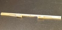
This is a Vee filing jig which can be FDM printed from the Templot template we created, it is easily made and very easy to use.

The two halves fit together holding the rail in position so a very accurate angle can easily be formed. These jigs can equally be used inconjuction with traditional track building methods, especially when non standard angles are required

View attachment 229786

Here is a finished joint still in the jig, un like more traditional methods you only file one side of the rail to allow it to fit in its locating slot in the A chair. And do the same one sided filing on the exit road rail

You can see the rail coming out of the jig on the right

View attachment 229787

You may need to read the description more than once if you are unfamiliar with the system

Common crossing chairs

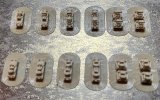
On the left are two prints for the loose jaw common crossing chairs and on the right is a set of fixed jaws common crossing chairs

View attachment 229788

To start off with I will use the fixed jaw set of chairs to help me check the length of the Vee rails and their fit

The two extra bits between the chairs are spacers, more about this later

View attachment 229789

I have fitted the common crossing chairs A, B & C then 2 bridge and 2 joint chairs. A crossing chair was fitted by Terry to test the slot, left in position so I don't loose it, no need to fit it at this time

View attachment 229790

One vee rail is fitted then cut to length, the second rail likewise will be fitted in position then cut to length

This is how I use the jigs:

index.php


You can let the back corner get worn away by frequent use without affecting further use of the jig.

Don't rub the file rapidly backwards and forwards. Make a firm forward cut, then lift the file away, and brush away the filings. Repeat.

More about using the Templot filing jigs at: https://85a.uk/templot/club/threads/1049

cheers,

Martin.
 

Hayfield1

Western Thunderer
I will re-awake this thread with the long awaited CARROT version of the Templot 3D track system.

The acronym stands for chairs and rusty rails on track, or putting it simply, making track building simpler and very much more accurate for the average modeler as well as speeding up the build process

532.jpeg

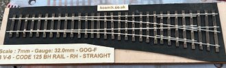
My first print in 7mm scale to Gauge 0 Guild fine standards, it is just as easy to set the gauge for Scale 7 or 00MF

537.jpeg

The turnout (B6) is made up of 3 sections and after cutting the rails to length, then preparing them, the rails are easily slid in place.

I have used Templot filing jigs for both the Vees and switch rails, the same program which makes the print files, will also make the jig files. These jigs are very easy to use and can be reused a few times

538.jpeg

A close up of the crossing and the added benefit of printing the wing rails is that they have bolt detail as well, the additional webs in the center aid height alignment of both printed and metal rails

Those wanting additional details can notch rail joints and add fishplates to the rail webs

Summing up well worth the wait

John
 

martin_wynne

Western Thunderer
I will re-awake this thread with the long awaited CARROT version of the Templot 3D track system.
@Hayfield1

We also now have the no-soldering 3D-printed switch drive bars (tie-bars). Epoxy or superglue fitting:

index.php


index.php


(Above is P4 4mm scale, 7mm is just the same.)

The timber ledges support a cover card hiding it below the ballast. Cosmetic scale stretcher bars can then be added to taste.

Martin.
 

Hayfield1

Western Thunderer
Martin

Having a senior moment, where do I find them please, I am at the back of the class with my dunces hat on

John
 

martin_wynne

Western Thunderer
Martin

Having a senior moment, where do I find them please, I am at the back of the class with my dunces hat on

John
@Hayfield1

Hi John,

Here:

index.php


Set medium or thick timbers first. In 4mm the medium bars are a bit thin, unless you cut away the webs. I will write some more shortly.

In 7mm should be ok with 0.4mm nozzle, but I haven't tested them. Will do.


In 7mm see also the BATTERY option for battery/radio control locos. Makes turnouts very cheap with no rails to buy:

https://85a.uk/templot/club/threads/1307

Martin.
 

Hayfield1

Western Thunderer
Martin

Thank you, an old dog learning new tricks

I tend to focus on what I know rather than fiddle about (though some may think different)

CARROT track is far better in hand than seeing photos of prototypes

My wife would love a battery train in the garden (I think not)

John
 

martin_wynne

Western Thunderer
On the turnout, I used thin superglue but epoxy may be better
@Hayfield1

Hi John,

I never get on very well with superglue and tend to prefer traditional 24hour epoxy for anything important, and then leave it overnight:


index.php

That's P4 4mm scale

There is a recess in the BAR chair for better glue grip, but that works only with a gap-filling adhesive -- which superglue is not (except perhaps superglue gel):

index.php


Also of course it is important to degrease the rail first, and maybe roughen the underside a little just where needed.

n.b. these drive bars are intended for use with track bases printed from the latest Templot version 557a. They won't fit so well in earlier bases, which might need some carving with a craft knife to fit, to allow space for the fixings to flex.

cheers,

Martin.
 

Hayfield1

Western Thunderer
536.jpg

Ian Allen is giving me a grilling aimed at how I design printable Templot COT & CARROT files, print and build them. A question and answer session from both Ian and other on line viewers. really a chat about how I end up with working turnouts

guildex 1.png

Terry and my self will be manning the Templot stand and hopefully Marti will be with us for part of the time on Saturday

We both are taking printers and will have computers with decent size PC/ desk Top monitors. Answering questions, showing how to and having samples of Plug, COT and CARROT formats to touch and see, mainly in 7mm but no doubt some 4mm examples as well

John
 

Hayfield1

Western Thunderer
542.jpeg

The 00SF A5 was easily finished off by adding rails, this one destined for a friend to test for me.

I must admit that I am very pleased with the CARROT system, as its very simple to build, much better than with COT track with those fiddly stub chairs. And as you would expect with a Templot design, works very well

Needs the FDM supports removed, bonding wires and tie bar fitting

John
 

martin_wynne

Western Thunderer
Do you glue the vees together?

If the rails are prepared in the Templot filing jigs for the angle which exactly matches the chairs, the vee rails can be pushed in firmly until they stop, and the chairs will grip them together.

But this works only if vee point rail is in the main road and is inserted first. It also needs to have been blunted back to the correct blunt-nose width. The vee splice rail in the diverging turnout road is then inserted second. The vee rails are therefore handed, need to be prepared as such for each V-crossing according to the hand, and won't work the other way round.

Glueing the actual rails together tends to be messy. It is better to apply a little glue to the underside of the rail a few timbers back from the nose, before pushing the rail fully home. The glue will be carried invisibly into the chair and lock the rail in position.

The same applies to the other rails. Pull them back a few mm, glue on the underside, push them forward again = invisible glue fixing in chair.

All easy to do once you know how. Likewise the rest of Templot 3D track. But knowing how means going on Templot Club forum and keeping up with developments.

cheers,

Martin.
 
Top