Highbridge and Dartmouth

Paul Townsend

Active Member
I contacted Kay who built this loco for advice on removing the motor so I can put the mech in Ultrasonic bath.
Here is her reply:

Hi Paul
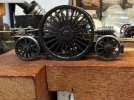
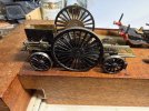
OMG it was as you say so long ago. This was constructed using very basic tools and very basic materials. For example, fair use was made of toothpaste tubes (lead) and perspex for the wheels. Spokes were formed with a piercing saw! The chimney was turned from lead in an electric drill. This was a first build and very limited information was available. I'm afraid I can't remember how the motor was installed but there must be some way to remove it. If you ruin the motor in the process, I'll send you a replacement.
Nice to think it still survives and is in safe hands.


Wow!
I guess that puts the build in early 1980s.

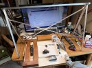
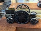
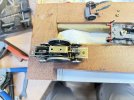
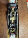
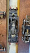
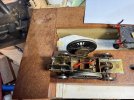
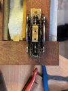
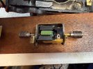
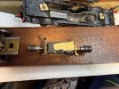
Here are pix of main sub-assemblies.
 

Attachments

  • IMG_3297.jpeg
    IMG_3297.jpeg
    91.3 KB · Views: 41
  • IMG_3299_reduced.jpg
    IMG_3299_reduced.jpg
    85.5 KB · Views: 41

Paul Townsend

Active Member
I said above that the wheels are EM.
One set of carry truck wheels are EM, other set are P4.
All now regauged to BGP4 min spec. B2B = 26.92mm for later running trial after mech cleaned.

My preference ( 50 years of P4 experience) is to set B2B to top of tolerance range, BGP4 = 27.00mm but Martin Goodall tells me that the thicker EM flanges run best at bottom of range B2B.
If I am not satisfied, I will change the EM set to P4 and increase all B2B to 27.00mm.

All this awaits a solution to motor removal and Ultrasonics.
 

jonte

Western Thunderer
Paul, the BG 4-2-4 is inspirational (to me, anyway).

As it appears that such a wonderful model was created from scratch with readily available materials such as Perspex and brass, it puts it in a class of its own.

Makes one want to roll up their sleeves and start huffing and puffing…….

Surely this is what modelling is all about?

Thanks for sharing.

Jon
 

Paul Townsend

Active Member
Next instalment in this saga::'(

Separating the main sub-assemblies of the chassis was easy.......just twiddling a nut runner.
The real challenge was removing the motor as I couldn't see how it was attached to the frame.
Much peering with extra light and magnification revealed 4 tiny screw heads covered in paint. I attacked these with a jewellers screwdriver.
2 were easily removed and turned out to be 12 or 14BA x c12mm, they will be measured in due course and replaced on reassembly to ensure the slots are in good nick. The other pair were pigs because they hide behingd the "9ft" spokes right at the tyre end. One wheel is partly removable to improve access. The other driver doesn't want to come out due to some wirey gubbins to do with the control of axle box in the hornblock.

With infinite patience I succeeded so now can go to the bubblebath.
Here are a bunch of pix showing the stages of disassembly.

Believe me this is a complex mech with drivers on stub axles, dummy inner crank axle parts and working rods and slide bars!
If Kay built this in 1980s it was decades ahead of its time in terms of the engineering features.
It must have taken many hundreds of hours to design, develop and build.

I am overwhelmed with admiration :'(
 

Attachments

  • 1_Chassis view.jpeg
    1_Chassis view.jpeg
    101.6 KB · Views: 38
  • 2_Dismantling.jpg
    2_Dismantling.jpg
    83.7 KB · Views: 35
  • 3_Major sub assemblies.jpg
    3_Major sub assemblies.jpg
    348.4 KB · Views: 31
  • 5_Drive Assy elevation.jpeg
    5_Drive Assy elevation.jpeg
    89 KB · Views: 31
  • 4_Drive Assy.jpeg
    4_Drive Assy.jpeg
    91.3 KB · Views: 32
  • 6_Drive Assy top.jpeg
    6_Drive Assy top.jpeg
    207.4 KB · Views: 31
  • 7_Drive Assy motor removed.jpeg
    7_Drive Assy motor removed.jpeg
    92.6 KB · Views: 33
  • 8_Dvr out & Crank axle.jpeg
    8_Dvr out & Crank axle.jpeg
    89.3 KB · Views: 35
  • 9_Motor in cradle.jpeg
    9_Motor in cradle.jpeg
    78.2 KB · Views: 37
  • 10_Motor cradle lugs.jpeg
    10_Motor cradle lugs.jpeg
    85 KB · Views: 37

AJC

Western Thunderer
That's a wonderful bit of work, hugely ingenious and a good solution to the single-driver adhesion problem by effectively making it an A1A with the stub axles getting the quartering separate from the wheels. The only shame, and I suppose that's a function of the date it was built, is the rather crude motor (a DS10? I suppose that's what was about that would fit), I am suitably in awe.

Adam
 

Paul Townsend

Active Member
A BGS member has referred me to an article in BGS Broadsheet (Brilliant Journal for such a small society) published in 1984 by the builder of this 9ft single....very informative.

I have tried this afternoon to remate the motor in its cradle back to the chassis. Easy enough to relocate it between the piston rods but to get the 4 tiny screws back is a bu$&er. One is started but others thru' the spokes has defeated me...try again tomorrow when fresh.
 

Phil O

Western Thunderer
Paul,

Where multiple bolts or screws are used, get them all started, by a couple of turns, before tightening them up, it gives a bit of wiggle room to get the others started.
 

Paul Townsend

Active Member
I agree and I can suck eggs too !! ;)

My problem is having had only one functioning eye for 9 months I am trying to learn strategies for allowing depth perception.
Chassis in a clamp, one hand holding tweezers with 12mm 14BA screw. other hand twiddling jewellers screwdriver, all between spokes and jammed up against the tyre. All that is challenging with 3D vision, without is "£$%^.

After Covid booster jab this am I will return to the job and all three screws will jump into place.
The sideframes are chunky by modern standards so one would hope the drilled clearance hole for 14BA would help keep screws orthoonal.
However those holes are slotted to allow slight freedom of movement of the motor cradle within the chassis while one meshes the worms and wheels. A very good idea once the screws are fully engaged; once happy with the mesh the screws would be tightened.......but first all 4 have to be started.:drool:
 

simond

Western Thunderer
Paul,

more eggs…

blu tack.
shrink wrap
sellotape
evostik

possible means of temporarily attaching the screw to the screwdriver tip

good luck!
Simon
 

Paul Townsend

Active Member
++P+aul,

more eggs…

blu tack.
shrink wrap
sellotape
evostik

possible means of temporarily attaching the screw to the screwdriver tip

good luck!
Simon
some of those I have used before so will work thru your list until job done
TVM
I have not yet revisited the job as I had a reaction to the jab ( first reaction in series of >12 jabs over 5 years.)
Also the BS4 mob have modelling day on Saturday. I haven't been to one for 3 years and am really looking forward to it.
Much preparation is required including building A-Frames so my worklight becomes mobile. Piccie below
Making the Aframes etc took all day today

Top ally strip carries the 3 led strips colour matched to the layout lighting so good for painting under.
Large VDU will NOT go to modelling day !

Space for spotlights too

I hope to get back to twiddling the 3 14BAs tomorrow. Any holdups means I take the loco on Saturday so chums can help.
 

Attachments

  • IMG_3310.jpeg
    IMG_3310.jpeg
    411.5 KB · Views: 13
Top