You are using an out of date browser. It may not display this or other websites correctly.
You should upgrade or use an alternative browser.
You should upgrade or use an alternative browser.
Hunslet Works in 7mm
- Thread starter Andy Ross
- Start date
Andy Ross
Western Thunderer
Hunslet Works update.
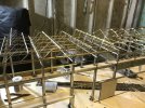
Following on from my last post it was time to fit all the new north light frames.
When I did this on the mock up some time back I relied on lining these up with the verticals in the cross beams and then just used a ruler to space out the purlins.
With the laser it was time to design and make some more jigs.
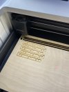
The cross beam jigs were designed to link into the ones that set the purlins.
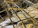
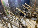
This made the job a lot quicker.
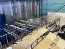
The roof looks a lot better with all these added.
I have also done the drawings and produces some trial parts for the wheel shop wall. This is made from plywood at the moment as it is quicker than MDF on the laser and this is just to prove the drawings, especially were the wall goes in between the crane supports.
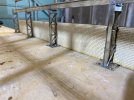
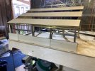
I have also fitted the wall the full length of the boiler shop. Photos to follow in the next update.
At the moment I am drawing the front end of the wheel shop which I am trying to get done before LarkRail on the Saturday 15th. But with two night working away this week I might not get it done.
If you do visit LarkRail please be sure to say hello.
Andy
Following on from my last post it was time to fit all the new north light frames.
When I did this on the mock up some time back I relied on lining these up with the verticals in the cross beams and then just used a ruler to space out the purlins.
With the laser it was time to design and make some more jigs.

The cross beam jigs were designed to link into the ones that set the purlins.


This made the job a lot quicker.

The roof looks a lot better with all these added.

I have also done the drawings and produces some trial parts for the wheel shop wall. This is made from plywood at the moment as it is quicker than MDF on the laser and this is just to prove the drawings, especially were the wall goes in between the crane supports.


I have also fitted the wall the full length of the boiler shop. Photos to follow in the next update.
At the moment I am drawing the front end of the wheel shop which I am trying to get done before LarkRail on the Saturday 15th. But with two night working away this week I might not get it done.
If you do visit LarkRail please be sure to say hello.
Andy
Last edited:
Andy Ross
Western Thunderer
Hunslet Works update.
One last push before LarkRail this weekend. See link below for details of the show.

 www.rmweb.co.uk
Over the last few days, in-between working on the layout I have drawing the front of the wheel shop.
I have modelled this how it was when there were still the sliding doors on the entrance to the erecting shop. A short section of the original shop had been left in place when the big lean too was added to the side of the erecting shop. Some time in the 70's this section was also demolished and a plain sheeted end was added.
I only have one part photo of this area in its last form, but several pictures of the old section still in place, so that's what I decided to do.
I have cut the parts from ply as this is only a test and I have found a few areas that need modifying but in the main it has gone together and fits.
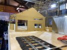
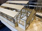
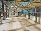
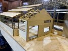
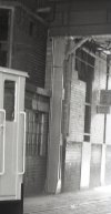
The photo through from the erecting shop matches well with the original photo.
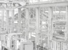
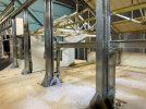
The photo also dates this round 1972 with the Scunthorpe Bo-Bo's on build.
It will be interesting to see how the layout will look fully populated when set up at this weekend show with all these extra bits on.
Andy
One last push before LarkRail this weekend. See link below for details of the show.

Larkrail 2023
Well, we've decided to do it all again! Details of what will be at this years Larkrail will be added later but rest assured there will be lots of lovely things to see and cake to eat. For now, just make a note in your diary. All proceeds will again be devided between Parkinsons UK and Julian Hous...
 www.rmweb.co.uk
Over the last few days, in-between working on the layout I have drawing the front of the wheel shop.
I have modelled this how it was when there were still the sliding doors on the entrance to the erecting shop. A short section of the original shop had been left in place when the big lean too was added to the side of the erecting shop. Some time in the 70's this section was also demolished and a plain sheeted end was added.
I only have one part photo of this area in its last form, but several pictures of the old section still in place, so that's what I decided to do.
I have cut the parts from ply as this is only a test and I have found a few areas that need modifying but in the main it has gone together and fits.


The photo through from the erecting shop matches well with the original photo.


The photo also dates this round 1972 with the Scunthorpe Bo-Bo's on build.
It will be interesting to see how the layout will look fully populated when set up at this weekend show with all these extra bits on.
Andy
David Waite
Western Thunderer
Hi Andy
Amazing work I’m enjoying following your progress.
I have in the distant past worked in many factories of the style that your model structure is
representing, you are capturing the industrial scene perfectly.
David.
Amazing work I’m enjoying following your progress.
I have in the distant past worked in many factories of the style that your model structure is
representing, you are capturing the industrial scene perfectly.
David.
Andy Ross
Western Thunderer
Hunslet Works - LarkRail - Bath.
The vist to LarkRail was a great success and some interesting discussions took place on how to present the layout at exhibitions.
The original plan for the weekend was to take the board and display it on a table as we had done at York at Easter. But on the way down from Leeds I had a lot of holds up in the traffic and this meant that I could not pick Peter Kirmond up on the way and he would have to meet me at the hall.
It struck me that this would mean that Peter could bring along a couple of trestles and we could possible display the board at a height nearer to what is planned for the layout when it is complete. Peter agreed it would be a good experiment to see how it would be received by the public.
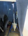
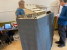
Peter also brought along the drapes from his York layout and it all made a real difference.
So did it work - yes it did - there were lots of positive comments, and the height we chose was ideal for operating the cranes, and high enough to allow visitors to look down the shop and get the full effect.
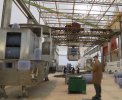
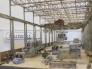
It also was a better height to get an appreciation of what you will be able to see through the side door.
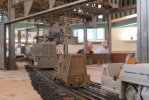
The Wheel shop structure also went down well, along with all the parts laid out in the shop.
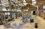
I also set up a shot that was similar to a real one from the erecting shop.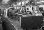
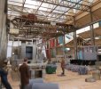
I was also busy with the laser just before the show, in fact the night before I set off. The end of the old wheel shop has the original slate roof, so it need all the timbers and lats on the inside. The photo of the old shop shows the detail that will be in the end section.
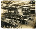
I have managed to recreate this by using the following. 2mm ply for the roof structure, 0.4 play for the lats and 1mm MDF for the timbers. These were all cut as a panel with a frame around the edge and then glued together.
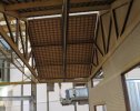
The effect when the panel is dropped in place is identical to the original. There will be a lot of these panels of various sizes to do as the roof sections of the North lights are tiled, as is most of the pitched section going towards the boiler shop.
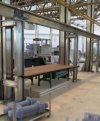
I have also cut some tops for the etched benches a few weeks ago and Jill has started to paint/stains these. I tried these in place in both the erecting shop and the wheel shop and again I am really pleased with these.
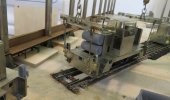
And last of all, Jill has produced some labels to go on the control boxes for the cranes which are going to make it easier for any trainee crane operator.
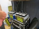
The good news is that Peter is now trained and signed off as competent as a crane drives for the double lift and wheeling so he is now a vital member of the operating team.
All in all it was a really good weekend and a excellent exhibition.
It was also good to chat with a few members from this group.
Next outing Swindon in September.
Andy
The vist to LarkRail was a great success and some interesting discussions took place on how to present the layout at exhibitions.
The original plan for the weekend was to take the board and display it on a table as we had done at York at Easter. But on the way down from Leeds I had a lot of holds up in the traffic and this meant that I could not pick Peter Kirmond up on the way and he would have to meet me at the hall.
It struck me that this would mean that Peter could bring along a couple of trestles and we could possible display the board at a height nearer to what is planned for the layout when it is complete. Peter agreed it would be a good experiment to see how it would be received by the public.


Peter also brought along the drapes from his York layout and it all made a real difference.
So did it work - yes it did - there were lots of positive comments, and the height we chose was ideal for operating the cranes, and high enough to allow visitors to look down the shop and get the full effect.


It also was a better height to get an appreciation of what you will be able to see through the side door.

The Wheel shop structure also went down well, along with all the parts laid out in the shop.

I also set up a shot that was similar to a real one from the erecting shop.


I was also busy with the laser just before the show, in fact the night before I set off. The end of the old wheel shop has the original slate roof, so it need all the timbers and lats on the inside. The photo of the old shop shows the detail that will be in the end section.

I have managed to recreate this by using the following. 2mm ply for the roof structure, 0.4 play for the lats and 1mm MDF for the timbers. These were all cut as a panel with a frame around the edge and then glued together.

The effect when the panel is dropped in place is identical to the original. There will be a lot of these panels of various sizes to do as the roof sections of the North lights are tiled, as is most of the pitched section going towards the boiler shop.
I have also cut some tops for the etched benches a few weeks ago and Jill has started to paint/stains these. I tried these in place in both the erecting shop and the wheel shop and again I am really pleased with these.


And last of all, Jill has produced some labels to go on the control boxes for the cranes which are going to make it easier for any trainee crane operator.

The good news is that Peter is now trained and signed off as competent as a crane drives for the double lift and wheeling so he is now a vital member of the operating team.
All in all it was a really good weekend and a excellent exhibition.
It was also good to chat with a few members from this group.
Next outing Swindon in September.
Andy
Last edited:
Osgood
Western Thunderer
There is so much I like about this (layout, working diorama?).
Detail such as the cast iron workbench legs, the 3-D printed diesel engines (are these your own 3-D drawn or scanned prints, or bought in items?).
How did you find the stability of the Draper-style metal trestles at what looks like almost maximum height?
If only I could have made it to Bath on Saturday!
Richard Gawler
Western Thunderer
Andy Ross
Western Thunderer
HiThere is so much I like about this (layout, working diorama?).
Detail such as the cast iron workbench legs, the 3-D printed diesel engines (are these your own 3-D drawn or scanned prints, or bought in items?).
How did you find the stability of the Draper-style metal trestles at what looks like almost maximum height?
If only I could have made it to Bath on Saturday!
Thank you for the comments.
The draper stands are really good. I have three at home and that is what I am building the layout on. There are a couple of clamps holding the board to the cross beams.
Now we have tried it at a show, Peter is looking at the proper legs which will be bolted onto the corners of the layout.
As for the 3d printing. I have drawn everything but the engines which I have downloaded. to be fair none of these were designed to be printed but I just gave it a go and they have come out ok. I will have to draw some up sometime as I need Rolls Royce C6 and C8's and some Gardner engines for the mines and Sudan locos.
Andy
paulc
Western Thunderer
Hi Andy , this is a masterpiece in metal ( plus a bit of resin ) . I will be in the UK staying in Aylesbury and will be visiting Swindon so its great that Hunslett works will be there .Hi
Thank you for the comments.
The draper stands are really good. I have three at home and that is what I am building the layout on. There are a couple of clamps holding the board to the cross beams.
Now we have tried it at a show, Peter is looking at the proper legs which will be bolted onto the corners of the layout.
As for the 3d printing. I have drawn everything but the engines which I have downloaded. to be fair none of these were designed to be printed but I just gave it a go and they have come out ok. I will have to draw some up sometime as I need Rolls Royce C6 and C8's and some Gardner engines for the mines and Sudan locos.
Andy
Andy Ross
Western Thunderer
Hunslet Work at LarkRail - Video added.
If you would like to see a small video of the layout see link below to SDJR7F88 link to his Video channel.
This is an excellent video from all around the show. The Hunslet section is at 3min 16sec in.
Thanks to Callum for sharing the link.
Andy
If you would like to see a small video of the layout see link below to SDJR7F88 link to his Video channel.
This is an excellent video from all around the show. The Hunslet section is at 3min 16sec in.
Thanks to Callum for sharing the link.
Andy
Andy Ross
Western Thunderer
Hunslet Works update.
I had a visit yesterday from Peter Kirmond who very kindly has made the baseboards for the layout.
We had measured up the previous weekend whilst at LarkRail for the lid for the protective side panel, and Peter had brought up the new lid to fit.
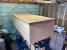
Peter had also brought along some spare legs. He had made these for his 2mm York layout but was not happy with the planned installation and had come up with an alternative.
He managed to fit some to the layout and although they need a couple of additional braces the fit really well.
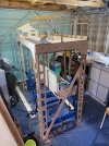
We will take these legs to Swindon as see what the reaction it to the height as it is a bit higher than what we had at LarkRail.
My thoughts are that it is were it needs to be, but I am open to comments.
At some point the same lags will be fitted to the other board. I am also currently looking at what we need for a small fiddle yard.
Andy
I had a visit yesterday from Peter Kirmond who very kindly has made the baseboards for the layout.
We had measured up the previous weekend whilst at LarkRail for the lid for the protective side panel, and Peter had brought up the new lid to fit.

Peter had also brought along some spare legs. He had made these for his 2mm York layout but was not happy with the planned installation and had come up with an alternative.
He managed to fit some to the layout and although they need a couple of additional braces the fit really well.

We will take these legs to Swindon as see what the reaction it to the height as it is a bit higher than what we had at LarkRail.
My thoughts are that it is were it needs to be, but I am open to comments.
At some point the same lags will be fitted to the other board. I am also currently looking at what we need for a small fiddle yard.
Andy
Andy Ross
Western Thunderer
Hunslet Works update.
Last weekend we took the new legs off and put the main board back onto the trestles.
The test track board was also connected using a trestle.
I have done this as I wanted to sort the structures on either side of the baseboard joint.
I have a drawing for the power room that will be over the test track on the narrow board, but I have very little information on the cross yard crane that originally came from the machine shop.
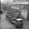
This means I need to build the powerhouse first. This buts up to to the wall that goes down the yard as can be seen in the photo with the loaded bogies. The plan was to sort that end of the wall and get on with the bridges. But as I pulled drawings off the original layout main drawing for detailing and adding structure I got carried away.
The results is that I have got up the yard past the entrance to the toilets in the pitched roof section.
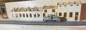
In total there are 23 different parts, some of which needed cutting several times.
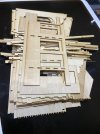
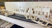
The Ideal is to make an inner frame that is braced with runners with 1/2 slots. the cross panels have slots and tabs into the false front.
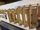
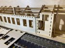
There is an outer layer with all the detail, bricks etc. At the moment these have been cut in 2mm ply but may be replaced with MDF. This will be decided when we have done some trials with the painting .
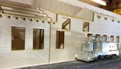
.
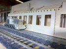
This took a lot of cutting and I found only a couple of errors so far that I have put right just incase we need to recut some part
s.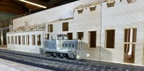
I am please with how it has come out as when you compare the photos with the real ones it all looks in proportion so far.
The loco is Mike Edges standard 388HP that I borrowed for LarkRail.
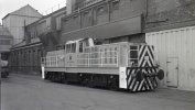
I must now leave this alone and get on with the other end that meets up with the main board.
For anyone wanting to see progress in the flesh we will be at the Swindon show at the Steam museum with the main board on the 9th and 10th September.
Unfortunaltley the Leeds exhibition has been cancelled this year due to building work at the venue.
Andy
Last weekend we took the new legs off and put the main board back onto the trestles.
The test track board was also connected using a trestle.
I have done this as I wanted to sort the structures on either side of the baseboard joint.
I have a drawing for the power room that will be over the test track on the narrow board, but I have very little information on the cross yard crane that originally came from the machine shop.

This means I need to build the powerhouse first. This buts up to to the wall that goes down the yard as can be seen in the photo with the loaded bogies. The plan was to sort that end of the wall and get on with the bridges. But as I pulled drawings off the original layout main drawing for detailing and adding structure I got carried away.
The results is that I have got up the yard past the entrance to the toilets in the pitched roof section.

In total there are 23 different parts, some of which needed cutting several times.


The Ideal is to make an inner frame that is braced with runners with 1/2 slots. the cross panels have slots and tabs into the false front.


There is an outer layer with all the detail, bricks etc. At the moment these have been cut in 2mm ply but may be replaced with MDF. This will be decided when we have done some trials with the painting .
.


This took a lot of cutting and I found only a couple of errors so far that I have put right just incase we need to recut some part
s.

I am please with how it has come out as when you compare the photos with the real ones it all looks in proportion so far.
The loco is Mike Edges standard 388HP that I borrowed for LarkRail.

I must now leave this alone and get on with the other end that meets up with the main board.
For anyone wanting to see progress in the flesh we will be at the Swindon show at the Steam museum with the main board on the 9th and 10th September.
Unfortunaltley the Leeds exhibition has been cancelled this year due to building work at the venue.
Andy
Osgood
Western Thunderer
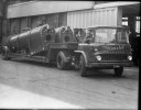
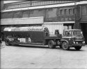
Interesting to note Hunslet ran a couple of lightweight low Loaders.
The only photo evidence I have seen of the Leeds builders suggests shows the use of hired-in transport to move std gauge locomotives, the majority of which required low loaders capable of carrying 30T plus - the realm of heavy haulage.
The only photo evidence I have seen of the Leeds builders suggests shows the use of hired-in transport to move std gauge locomotives, the majority of which required low loaders capable of carrying 30T plus - the realm of heavy haulage.
Last edited:
Andy Ross
Western Thunderer
We still had an one artic in the 80's - I think it was a Seddon Atkinson but I can not find any photos.Interesting to note Hunslet ran a couple of lightweight low Loaders.
The only photo evidence I have seen of the Leeds builders suggests shows the use of hired-in transport to move std gauge locomotives, the majority of which required low loaders capable of carrying 30T plus - the real of heavy haulage.
I have found a few more shots of the Bedford's.
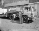
Last edited:
Mike Garwood
Western Thunderer
Having seen this at layout at Larkrail last month. I'd just like to say how much I enjoyed watching it. Absolutely spell binding! A fantastic concept carried out with such skill. Looking forward to seeing more developments.
Mike
Mike
Andy Ross
Western Thunderer
Hunslet Works Update
Following on from the previous post I needed to get on with the bridge section on the narrow board as this will determine the position etc for the similar section on the main board.
Again this was to be constructed from laser cut parts. There was a lot of drawing needed for this and I had to ensure it could extend over the track without a supporting leg on the outside edge of the baseboard.
I started cutting parts on the Thursday evening and finished on Friday.
There were some modifications and improvements I identified as I went along and these will be explained below.
Three main sub assemblies were created first.
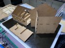
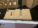
There were a lot of tabs and slots designed in and amazingly they all lined up.
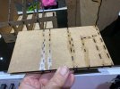
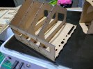
The section with the recesses is the wall under the bridge. The original plan was to produced this by layering up the same profile but was missing brick detail and I did not got it all quite in line. The redraw did take quite a while but the end result is much better.
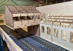
The main assembly went easier than expected with just a couple of small adjustments to allow for a build up of tolerances and a couple of packers that were needed to fill in a gap created by the redesign of the wall.
I have dropped it on the layout and I am really pleased with it.
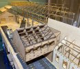
I am also pleased with the wall with the cable ducts.
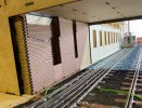
I also had to take a few shots with locos to get a real feel for it.
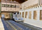
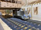
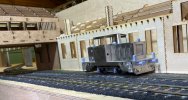
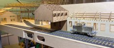
The bridge has came out about 10mm in from the edge of the baseboard - I don't think anyone will notice at exhibitions and to be fair I think it is better as it will not be so vulnerable to being knocked.
The next job is the other bridge section on the main baseboard.
With all this progress we are looking to take the test track board to Swindon on the 9th and 10th September as well as the main board if I can get it in the car without a proper crate for it.
Andy
Following on from the previous post I needed to get on with the bridge section on the narrow board as this will determine the position etc for the similar section on the main board.
Again this was to be constructed from laser cut parts. There was a lot of drawing needed for this and I had to ensure it could extend over the track without a supporting leg on the outside edge of the baseboard.
I started cutting parts on the Thursday evening and finished on Friday.
There were some modifications and improvements I identified as I went along and these will be explained below.
Three main sub assemblies were created first.


There were a lot of tabs and slots designed in and amazingly they all lined up.


The section with the recesses is the wall under the bridge. The original plan was to produced this by layering up the same profile but was missing brick detail and I did not got it all quite in line. The redraw did take quite a while but the end result is much better.

The main assembly went easier than expected with just a couple of small adjustments to allow for a build up of tolerances and a couple of packers that were needed to fill in a gap created by the redesign of the wall.
I have dropped it on the layout and I am really pleased with it.


I am also pleased with the wall with the cable ducts.

I also had to take a few shots with locos to get a real feel for it.


The bridge has came out about 10mm in from the edge of the baseboard - I don't think anyone will notice at exhibitions and to be fair I think it is better as it will not be so vulnerable to being knocked.
The next job is the other bridge section on the main baseboard.
With all this progress we are looking to take the test track board to Swindon on the 9th and 10th September as well as the main board if I can get it in the car without a proper crate for it.
Andy
Last edited:
Andy Ross
Western Thunderer
More progress so far this weekend.
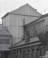
During the week while I have been away for my day job I managed to get the drawings done for the tower.
I cut the parts out last night when I got home and assembled it this morning. I will admit that I managed to get some of the slots out of place and completely missed some. So there was a bit of recutting this morning.
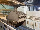
This has to to be removable for transporting so the assembly slots into the back of the bridge section.
It was a bit tight but with a but of sanding it now drops in nice a snuggle.
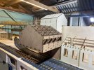
I have scored some lines on this to act as a guide for when I add the corrugated sheets.
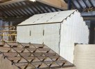
I have also today been looking at the main doors. I have not been happy with these as they have been very noisy and a little slow to operate.
The original design was to use the small motor gearboxes that a lot of us have found all kind of uses for - I use them to drive the cranes. But for some reason no matter what I did they were very noisy when working.
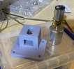
I had recently found an all enclosed unit on eBay and today I fitted one to see how we got on. It is a lot better and with it being a bit bigger the gearbox fits right up onto the baseboard and at the moment it is held in place with some double sided tape.
See video link below.
https://youtu.be/IBiPVwt899o
I had bought two gearboxes but the other one is faulty so I have found the same thing on Amazon and hopefully this will arrive tomorrow.
Tomorrow I need to service the cranes ready for Swindon as this is only a couple of weeks away.
I have also arranged with the organiser to now take both boards to the show.
Andy
During the week while I have been away for my day job I managed to get the drawings done for the tower.
I cut the parts out last night when I got home and assembled it this morning. I will admit that I managed to get some of the slots out of place and completely missed some. So there was a bit of recutting this morning.

This has to to be removable for transporting so the assembly slots into the back of the bridge section.
It was a bit tight but with a but of sanding it now drops in nice a snuggle.

I have scored some lines on this to act as a guide for when I add the corrugated sheets.


I have also today been looking at the main doors. I have not been happy with these as they have been very noisy and a little slow to operate.
The original design was to use the small motor gearboxes that a lot of us have found all kind of uses for - I use them to drive the cranes. But for some reason no matter what I did they were very noisy when working.

I had recently found an all enclosed unit on eBay and today I fitted one to see how we got on. It is a lot better and with it being a bit bigger the gearbox fits right up onto the baseboard and at the moment it is held in place with some double sided tape.
See video link below.
https://youtu.be/IBiPVwt899o
I had bought two gearboxes but the other one is faulty so I have found the same thing on Amazon and hopefully this will arrive tomorrow.
Tomorrow I need to service the cranes ready for Swindon as this is only a couple of weeks away.
I have also arranged with the organiser to now take both boards to the show.
Andy
Last edited:
michael mott
Western Thunderer
Andy What an amazing piece of model work ......no model engineering! I wish I was in the UK and could see it in the flesh.
Michael
Michael


 ) . . . it is a wonderful project.