Inside valvegear in 7mm. Techniques and components

Rob Pulham

Western Thunderer
Hi Steph, I for one would be interested.

I really do fancy having a go at inside motion and I have just won some Shedmaster nickel parts on eBay yesterday but they haven't arrived yet so I am not quite sure what I have for my money yet. I will post some photo's once they arrive.
 

Steph Dale

Western Thunderer
Rob Pulham said:
Hi Steph, I for one would be interested.

I really do fancy having a go at inside motion and I have just won some Shedmaster nickel parts on eBay yesterday but they haven't arrived yet so I am not quite sure what I have for my money yet. I will post some photo's once they arrive.

He he, you got them did you?  I think there are some Sans Pareil bits in that lot too from looking at the photo.  The Shedmaster parts are the same as those now available from Laurie Griffin and include the eccentrics, eccentric straps and various other parts I've been 'playing' with.  The cranks on the 2251 crank axle are actually old Shedmaster ones (made in phosphor-bronze).  The newer versions appear to be in nickel-silver and a touch slimmer, so need less fiddling...

Steph
 

Rob Pulham

Western Thunderer
I was watching the Javelin kits too. Not that I was interested in buying them but I did wonder if you would be in the running. All I need is a kit that needs inside motion.
 

Steph Dale

Western Thunderer
Rob Pulham said:
All I need is a kit that needs inside motion.

Rob,

Quote of the day that, I think!  ::) 

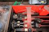
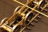
There is considerable variety in Stephenson valvegear, some is relatively simple to model (MR), some is tricky (LSWR), some is a downright nightmare (anything with rocker-shaft valve drive, including later Maunsell locos) and most have some little quirk (Ashford locos all having left-hand lead; Eastleigh and Brighton all having right-hand lead: Ashford even re-set the cranks on their Terrier, it's how you can tell the crank axle in 'Boxhill' comes from this loco) 

I can recommend the relevant articles that were published by the HMRS (throughout Vol14 of the HMRS Journal) 'Steam locomotive valve gears' by John Hull: I got hold of a set of photocopies (now very faded so impossible to further copy, I'm afraid) just by writing to the HMRS Publications Officer.  If you get further interested in (prototype) valvegears then 'Locomotive Valves and Valve Gears' by C.S.Lake and A.Reidinger (pub. Percival Marshall in Nineteen Umpty-ump) is worth tracking down.

I also have to say that these days I wouldn't build a loco with inside valvegear unless I had access to a reasonable General Arrangement or Motion Arrangement.  Thankfully many are relatively easy to get hold of these days through the NRM 'Search Engine' Microfilm Collection.  Some are even published in specialist mags and books!

Steph
 

Steph Dale

Western Thunderer
In that case, a wee taster:

30120's most intimate bits as taken earlier this year at the Flour Mill. You may notice some potential pitfalls for the unwary modeller. And yes, I fell in a couple of them already, which is why I'm now looking to start the third motion bracket pattern. Even the prototype has fag-paper clearances... :headbang:

Oh, and if you're the owner of a model T9, look away now. Yep, they all got this bit wrong. :shit:

Steph
 

Attachments

  • IMG_3855.JPG
    IMG_3855.JPG
    84.8 KB · Views: 103

3 LINK

Western Thunderer
Fantastic piece of engineering there  :bowdown: :bowdown:, and as for your other query Steph regarding the Great Central, I cannot recall exactly if the gent I am thinking of could have possibly been your father as I was probably still dribbling over the 8f pulling a train of 16t minerals  :drool: :thumbs:.

ATB,  Martyn.
 

Steph Dale

Western Thunderer
Yep, the quality of the engineering/restoration is superb.  I'll have to get down to Bodmin to see the grand old lady in action when I get the chance.  Now I just need to work out how to make all that gubbins 43 times smaller...

Steph
 

Steph Dale

Western Thunderer
Hi guys,

I thought that having made a some more progress recently it might be worth a little update to this thread.

Having made the crank axle a while ago, I have now moved on to building the rest of the chassis so that it can be fitted. Using the newer Laurie Griffin or MOK components will get you to a 20mm width across cranks. Which as the photo shows gives ample room for hornblocks and the necessary beams for this chassis, if some care is taken.
 

Attachments

  • IMG_8055.JPG
    IMG_8055.JPG
    86.4 KB · Views: 109

28ten

Guv'nor
The MOK cranks look to be the business  :thumbs: but please tell me you will do something about the crank pins  :)) :))
 

Steph Dale

Western Thunderer
28ten said:
The MOK cranks look to be the business  :thumbs: but please tell me you will do something about the crank pins  :)) :))

The MOK cranks certainly are terrific, I had a good look at a set a few weeks ago when helping a mate make a set up onto an axle (also using Loctite 638).  They may have a problem with the phasing of the eccentrics, but only a few anoraks would be able to tell.  The ones in the photo are the new pattern Laurie Griffin ones; assembled to give the correct phasing of the eccentrics.

A stern talking to is already in the pipeline for the crankpins: so too a pack of CPL crankpin nuts and a date with a pair of flush cutters...  ;D

Otherwise, what have I missed?  :scratch:

Steph
 

Steph Dale

Western Thunderer
Right then. Today I may well have broken the back of the valvegear build, although there's still some way to go...

After making the crank axle it struck me that the next most critical item in the assembly was the positioning on the slidebars and cylinder back. If this assembly is too close to the crank axle or out of alignment with it then there's a significant chance of crossheads running into the cylinder back or connecting rods hitting the slidebars at top or bottom dead centre. Of course, if the assembly is too far forwards then the crossheads can come out of the back of the slidebars. None of these are in any way desirable.

So yet again a jig was made up to make this part of the assembly easier. It's a fairly straightforward design for this loco with simple slidebars; locos with 4-bar, trough or single slidebars would require some modification to this design, in order for it to interface effectively with the slidebars themselves:
 

Attachments

  • IMG_8077.JPG
    IMG_8077.JPG
    104.3 KB · Views: 109
  • IMG_8078.JPG
    IMG_8078.JPG
    88.9 KB · Views: 120
  • IMG_8079.JPG
    IMG_8079.JPG
    78.1 KB · Views: 108
  • IMG_8080.JPG
    IMG_8080.JPG
    77.7 KB · Views: 107
  • IMG_8081.JPG
    IMG_8081.JPG
    85.1 KB · Views: 109
  • IMG_8082.JPG
    IMG_8082.JPG
    96.3 KB · Views: 109
  • IMG_8084.JPG
    IMG_8084.JPG
    73.5 KB · Views: 108
  • IMG_8085.JPG
    IMG_8085.JPG
    55 KB · Views: 109

3 LINK

Western Thunderer
Hi Steph,

B***dy good idea you have there, it certainly keeps everything in line, ie :- the non moving parts which after all are just as important as the links and rods when it comes to building smooth running valve gear. Interesting thread keep up the good work,

ATB,  Martyn.  :thumbs:
 

Dan Randall

Western Thunderer
Crikey Steph, what an excellent idea!  I'll certainly be blagging that when I build a loco with inside motion.  :thumbs:


Regards

Dan 
 

Steph Dale

Western Thunderer
Hi guys,

Pleased to be of service... :))

I can't admit to any of it being 'clever' - but does indicate a certain degree of malice aforethought, here's tonight's installment. I really am cracking on with this aren't I? Oh well, it can't last...

Last night I left it looking something like this, all nicely bracketed off the front spacer:
 

Attachments

  • IMG_8086.JPG
    IMG_8086.JPG
    99.8 KB · Views: 102
  • IMG_8087.JPG
    IMG_8087.JPG
    101.9 KB · Views: 103
  • IMG_8088.JPG
    IMG_8088.JPG
    104 KB · Views: 105
  • IMG_8090.JPG
    IMG_8090.JPG
    111 KB · Views: 105
  • IMG_8091.JPG
    IMG_8091.JPG
    79.2 KB · Views: 96

Dog Star

Western Thunderer
Dot marking items to ensure items are re-asssembled as fitted is a good idea, so one dot left and two dots right, :)  What do you propose to do so that you identify front / middle / rear in the case of axleboxes (or leading / driving / trailing for a six-coupled engine from Swindon)?  Maybe small punches for LL, LD, LT, RL, RD, RT would be a nice touch,  ;D

Not being diffficult, just wondering if you have an answer to a problem which is wandering around the workbench.

regards, Graham
 

Steph Dale

Western Thunderer
Graham,

I have stuck with the 'dots' method for now; the 2251 which attaches to this set of valvegear actually has different hornblocks on each axle:
Leading axle has a set of very slimmed insulating hornblocks
Middle axle has a set of very thinned brass hornblocks
Rear axle has a set of nearly-full-thickness insulated hornblocks

So on this loco I can get away with just 'one dot left and two dots right', as you point out.

On other locos, which have less variety in their running gear I've stuck with the 'dots' method: all marked on the bottom of the hornblock.  The sequence/pattern you adopt is of course up to you: I simply give them between 1 and 6 dots and put all the even numbers on one side.

I must admit I do like the idea of using a set of number/letter punches though: they're one of those things I haven't got and every now and again think of a particularly splendid use for them...  :scratch:

Steph
 
S

Simon Dunkley

Guest
Not 7mm (smaller!) and not GWR, but the photo below shows some of the constructional details of the working inside valvegear fitted to an S scale GER T26 (LNER E4) 2-4-0 built by Trevor Nunn.

The motion unit is removable, and soldered to thin single-sided PCB. It is held in place either side with a screw into in a captive nut, which is electrically insulated from the rest of the motion as the loco has split axles and split frames. The screw heads are hidden behind sandboxes when the body is in place.


Attachments

  • T26vg.JPG
    5.8 MB · Views: 27

bogusman

Western Thunderer
Hi Steph the motion certainly looks good in 7mm. I like the way your eccentric straps split like the real thing unlike the 4mm Finney Collett I am building at the moment where the eccentric rods, eccentrics and cranks all had to be fitted to the axle set with a vernier and then silver soldered as a complete unit :eek:.

Pete 
 
Top