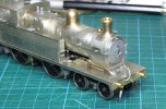
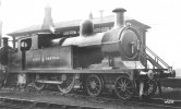
Latest project: ex-LNER C13, No. 67421

Dave Holt

Western Thunderer
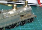
Front frame extensions and the curved cover between have been fixed in place. Apart from the lamp irons, a couple of more lubrication pipes and the VCR vacuum actuator, oh, and the steam heating cock, the front end of the loco is now finished.
looking more and more like a C13.
The diagonal pipe on the LH side of the boiler is the steam feed to the atomisers, I think.
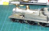
C13_149.JPGC13_150.JPGC13_151.JPGC13_152.JPG
Dave.
 

LarryG

Western Thunderer
67421 was shedded at Gorton in the mid 1950s and frequently worked the Guide Bridge to Oldham or Stalybridge push-pull services. I've just imagined that either of these could have been extended to Delph (or Holt, as my imaginary version is called). Such workings would have been perfectly feasible with the existing trackwork although they didn't actually occur.
Dave.
It was weird that BR did not use its advantage of removing old company boundaries. But whether a Delph - Stalybridge - Guide Bridge service would have been useful via Oldham is open to question. Delph-Stockport would probably have been more useful particularly if Moorgate Halt had been promoted as the station for Uppermill and been better served.
 

Dave Holt

Western Thunderer
Good point, Larry. The Delph - Stalybridge - Stockport service would suit my imaginary scheme. Would affect which end the loco was at compared with routing via Oldham? I don't think so as photos show loco first at Clegg Street and Stalybridge, so loco first into Delph, same as the Donkey.

Dave.
 

Dave Holt

Western Thunderer
Help!
I've become aware that 67421 in the period modelled (mid 1950s) appeared to have been fitted with a cab roof from a C14. The main difference is the lack of the C13 inverted T-section stiffening rib and the provision of a sliding ventilator running in transverse guide strips.
Does anyone have any decent photos or drawing information of the C14 roof ventilator arrangement?
Dave.
 

Dave Holt

Western Thunderer
Well, I had a couple of very helpful replies to this same question posed in the Questions section (thanks guys) and also drawing information from Mike Edge, of Judith Edge Kits, who do a C14 kit in 4 mm scale.
As a result, a ventilator arrangement has been sketched out and suitable artwork created by Rumney Models covering the options of ventilator closed or open.
All I have to do now is summon up the courage to try and remove the external stiffener from the roof, hopefully without causing any collateral damage and possibly cut a largish rectangular hole in the middle of the roof.
Dave.
 

Dave Holt

Western Thunderer
Delivery of some additional and revised etched and printed parts from Rumney Models has prompted a bit more progress with this loco.
The cab roof now has its sliding ventilator, set in the fully open position, and I've also added rain strips along each side.
C13_158.JPG
The foot steps under the footplate, the water balance pipes and the steam heating pipes have been fitted.
C13_156.JPGC13_157.JPG
I've had to chop off the ends of the rear tank support brackets to clear the balance pipes during assembly/disassembly. With hindsight, perhaps the balance pipes and rear foot steps should have been mounted to a plate fixed to the chassis below the foot plate, as this would also allow the injector overflow pipes to be fixed under the lower tread of the steps. Too late now.
You might notice that the printed sand boxes, previously attached to the chassis, have been removed. I had become aware, from studying photos of my chosen prototype, that by the mid 1950s, the original , deep C13 boxes had been replaced by the shallower type fitted to C14s. Revised prints have been produced and await preparation and fitting.
Dave.
 

Dave Holt

Western Thunderer
A few more details added including the push-pull VCR actuating mechanism, the missing steam feed pipes to the atomisers, injector overflow pipes and the new C14 style sand boxes.
View of the LHS showing the VCR gear and a hint of the shorter front sand box.
C13_159.JPG
RHS where the steam feed to the RH atomiser can just be made out going to the top connection.
C13_160.JPG
Not too much more to do on the body now - fit the fire iron rests on the LH tank top and sort out the number and shed plate fixings.
Still a bit to do on the chassis.
Dave.
 
Last edited:

Dave Holt

Western Thunderer
Thanks, Chas. Yes, I think the C13s were a good looking loco - and much larger than one might think. I'm quite pleased with the way the model is turning out.
Here's a side on photo I had forgotten to save as a re-sized file. The small sand boxes are more apparent here. Compare with post 141.
C13_161.JPG
I've now attached the etched balance weights to the wheels. Impressive difference in shape and position between the front diving axle and the rear coupled axles (though on the model it's actually the rear axle that's driven!)
C13_162.JPG
Dave.
 

Dave Holt

Western Thunderer
Final details added to the body which is now complete, ready fro painting.
The final bits fitted were the tank top fire iron rests. Mine aren't quite as spinddly as the prototype because I want them to have a bit of strength against minor knocks.
Here we see a sort of C13 glove puppet.
C13_163.JPG
And a closer shot of the front rest.
C13_164.JPG
Still a few bits to do on the chassis - steam heat cocks and the dreaded sand pipes. I've designed some etched brackets for the latter, so there will be a wait for final completion. I can get on with painting chassis in the mean time.
Dave.
 

Dave Holt

Western Thunderer
No, Morgan. I'll paint the chassis but the body painting, lining/numbering and weathering will all be done by David Clarke.

Dave.
 
Top