Michael's Werkbank (Bavarian PT2/3)

michael080

Western Thunderer
Evening Folks,

I have been lurking here for some time and had a few threads of my builds, so I thought it might be time to start my own workbench thread. As there are quite a few Michaels around here, I thought I might distinct my workbench a bit languagewise.

First project here will be a Class40 kit, designed by David Parkins, published and originally sold in the early 2000s. I had a chance to pull it from someones stack and push it on my own a year ago and decided that now is the time for 480mm long loco.

Right now, I am browsing photo galleries to find a frequently photograped prototype to supply the necessary detail information about an individual prototype. Located in Germany, I have no "home line" where I have already been trainspotting as a boy, so I am quite open. I like the green livery, so it will be likely a machine in its early live.

My first question to the assembled community: Has there ever been a build thread for this kit? Browsing through the manual leaves questions unanswered.

I have been considering various options how to motorize the kit. With 8 axis, there are a few possibilities, but I think Davids proposal to only drive the innermost axis of every bogie is not the best. You can put as much weight on the body as you want, you will always get only a small fraction on the driven axle. So currently I think motorizing the kit as 1 (A 1 A) (A 1 A) 1 with two motors might be better.

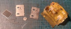
Long posting, no pictures yet, so here are few examples of the magnificent frets in the kit.

first the huge main body fret. The body ends will be resin parts. I will see how to bend the radius between floor and walls.

IMG_20220816_205517_DRO_cr.jpg

These are the outer bogie parts. Eight pieces, for two bogies, the fret has 0.6mm, so the side plates will be 1.2mm after sweating them together.
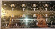
IMG_20220816_205302_DRO_cr.jpg

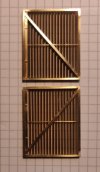
This is the very delicate nickel silver fret. Part 54 is the louvre covering the ventilation air ducts. You can see the 10x10mm pattern on my desk pad.
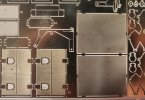
IMG_20220816_205406_DRO_cr.jpg

I will post as frequently as possible, but I am not the most diligent writer....

Michael
 

Yorkshire Dave

Western Thunderer
Hi Michael

If I was going to drive the loco I would go down the A1A-A1A route using the Finney7 SDMP power and remote gearboxes. A PDF planning template is available as a download as are the instructions.

Personally I prefer these as I've never got on with the more popular delrin chain drives. I suppose the ultimate challenge and drive would be 6 axle hung motors and gearboxes as the prototype. :)

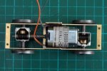
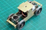
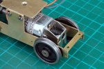
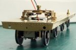
Below are photos of the Finney7 power and remote I've used in a B-B drive unit (64.75mm axle centres) and how the top of the 1833 motor is almost flush with the top of the chassis.

Met 49.jpg

Met 44.jpg

Met 45.jpg

The bogie/drehgstell mounting was reduced in height (below) and further still (bottom).

Met 51.jpg

Met 52.jpg
 

michael080

Western Thunderer
Dave,

that are exactly the gear boxes I had in mind. The two rectangular cutouts in the picture of the main body give some space for the motors. I have still 3 Mashima motors here and the gear boxes have been ordered at the Finney7 crew. I hope it won't take to long to get them. I might start with the cab interiors until then.

But first in the queue is the unfinished LMS 30 ton bogie bolster.

Michael
 

michael080

Western Thunderer
Hi,
a little update.

IMG_20220908_192943_cr.jpg

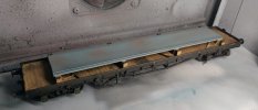
I have brought my bogie bolster wagon almost to completion, but now I try to figure out how to lash down the steel plates on the bolsters. I have browsed a lot of pictures, but most of the time, you can only see a dark lump of chains without any clear detail.

I assume that the wagons latching accessories were made up of
-- pieces of chain,
-- hooks on one end,
-- shackles at the side of the wagon,
-- devices to frap (?) the chains.
Sorry, this is not my standard vocabulary, I have no idea how these things are called.

Would the stakes (?) be set into position, even if the plates would be latched?

Any info is highly appreciated.

Btw., the steel plates are lead sheets cut to size. They are 1.25mm thick which is close to prototypical 5". They add almost 300g of weight to this long wagon.

Regarding my Class 40 kit, is there a problem with Finney7, I have concated them by mail, sent a reminder, but no response at all....

have a nice evening,
Michael
 

Dog Star

Western Thunderer
I assume that the wagons latching accessories were made up of
-- pieces of chain,
-- hooks on one end,
-- shackles at the side of the wagon,
-- devices to frap (?) the chains.
Sorry, this is not my standard vocabulary, I have no idea how these things are called.
Look at the CPL website... amongst the various wagon couplings... there is one product for chaining containers to wagon bodies. The GWR referred to this item as "binding" chains. I provided the relevant GWR drawing to Pat Legg when she owned CPL, Pat had masters made by Tony Reynalds, castings from Tony's patterns are sold by the current-day CPL.
 

Yorkshire Dave

Western Thunderer
Hi Michael

As far as I'm aware there are no issues with Finney7, however they were in attendance at the 2 day O gauge show at Stafford last weekend. I would try sending a personal message (PM) to @Dikitriki on this forum.
 

michael080

Western Thunderer
@Graham,
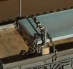
thanks for the link, i have 3d-printed the binding chains. Actually, the MMP-kit had whitemetal parts, but they were so soft and flimsy that I didn't want to use them. I have latched down the steel plates with chains and the binding chains attached to the binding rings. No idea if it is authentic, but it appears to be the logical way to fix the plates from shifting.

DSC06591_cr.jpg

DSC06593_cr.jpg

the expert will notice that the springs in the bogies are missing. I have been trying for a couple of hours to place 8 springs simultaneously into their bearings. No success. :rant:

The clamps to fix the trapaulin are also 3d-printed. The MMP parts were too small for my soldering iron and for my eyes. :-(

@Dave,
Simon and Richard contated me independently in between. All settled, my gearboxes are hopefully already on their way.
I guess I will start with the cabin until they arrive.

Michael
 

djparkins

Western Thunderer
@Graham,
thanks for the link, i have 3d-printed the binding chains. Actually, the MMP-kit had whitemetal parts, but they were so soft and flimsy that I didn't want to use them. I have latched down the steel plates with chains and the binding chains attached to the binding rings. No idea if it is authentic, but it appears to be the logical way to fix the plates from shifting.

View attachment 170512

View attachment 170513

the expert will notice that the springs in the bogies are missing. I have been trying for a couple of hours to place 8 springs simultaneously into their bearings. No success. :rant:

The clamps to fix the trapaulin are also 3d-printed. The MMP parts were too small for my soldering iron and for my eyes. :-(

@Dave,
Simon and Richard contated me independently in between. All settled, my gearboxes are hopefully already on their way.
I guess I will start with the cabin until they arrive.

Michael

Michael,

Actually the 'white metal' parts for the screw tenshioners and all the rings/shackles etc. are just about 2% short of pewter which is very strong and won't break. It doesn't have to actually keep your load in place anyway, as presumably you have fixed the the wagon load to the bolster tops.

For the life of me I cannot see why you think you need to hold 8 springs in place unaided. They springs clip over the tabs on parts 6 & 7. If you place a little Evo-Stik or other contact adhesive onto the tabs on part 7 [after parts 8 have been fitted over the tabs], then these will stay in place until you complete that part of the assembly and the addition of each of the parts 6 will then automatically trap the springs in place. You can do it the other way and glue the springs over the tabs in part 6, then adding the assembly made from parts 7 and 8, but the result will be the same - absolutely no need to hold 8 springs in place.

Why would you try and solder the tarpaulin hooks - they can be quite adequately fitted with Loctite or Zap and several spares are included.

Regards

DJP/MMP
 

michael080

Western Thunderer
Michael,

For the life of me I cannot see why you think you need to hold 8 springs in place unaided. They springs clip over the tabs on parts 6 & 7. If you place a little Evo-Stik or other contact adhesive onto the tabs on part 7 [after parts 8 have been fitted over the tabs], then these will stay in place until you complete that part of the assembly and the addition of each of the parts 6 will then automatically trap the springs in place. You can do it the other way and glue the springs over the tabs in part 6, then adding the assembly made from parts 7 and 8, but the result will be the same - absolutely no need to hold 8 springs in place.

Why would you try and solder the tarpaulin hooks - they can be quite adequately fitted with Loctite or Zap and several spares are included.

Regards

DJP/MMP


David,

it's an honour to see that the designer of my favourite kit brand comments on my amateurish results.

The problem with the springs is that they do not glide freely onto the tabs provided. You can arrange them to stand upright and parallel on one side, but as soon as you flip the other side with the opposite tabs over, the springs will evade in all directions. This is because they need to be guided precisely into the correct direction. It would be easier if the receiving tabs were trapezoid to catch the springs. I noticed that only after everything was folded up, so I couldn't modify the tabs at that stage. I guess my fingers are a bit too clumsy for the job.

Same with the tarpulin hooks, no way to fix them with my fingers. I think my 3d-printed replacements look pretty much like the prototype, why not modifying a kit where it is possible with my own skill.

Bol16_cr.jpg

Michael
 

djparkins

Western Thunderer
David,

it's an honour to see that the designer of my favourite kit brand comments on my amateurish results.

The problem with the springs is that they do not glide freely onto the tabs provided. You can arrange them to stand upright and parallel on one side, but as soon as you flip the other side with the opposite tabs over, the springs will evade in all directions. This is because they need to be guided precisely into the correct direction. It would be easier if the receiving tabs were trapezoid to catch the springs. I noticed that only after everything was folded up, so I couldn't modify the tabs at that stage. I guess my fingers are a bit too clumsy for the job.

Same with the tarpulin hooks, no way to fix them with my fingers. I think my 3d-printed replacements look pretty much like the prototype, why not modifying a kit where it is possible with my own skill.

View attachment 170662

Michael

Yes, your tarp hooks look great Michael. I was just saying in general that I never solder smaller details like that, where you have a location tab for them.

David
 

michael080

Western Thunderer
Still waiting for the gear boxes to arrive, but I started with some bits and pieces around the resin cab ends.

IMG_20220919_203145_cr_sml.jpg

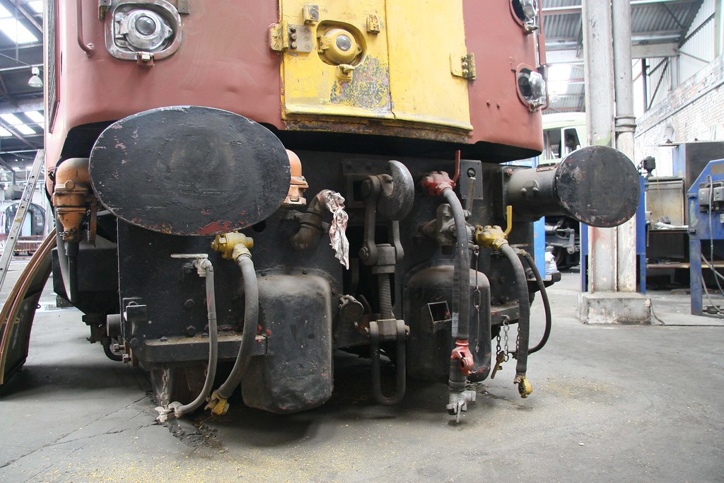
I am wonderring how the headcode discs are actually mounted. Are they following the curved shape of the cabin or are they perpendicular to the direction of travel?

The nickel silver fret is fantastic. Only 0.2mm thick. The grill on the upper left has all segments of the shutter bend out by 45°.

Michael
 

michael080

Western Thunderer
well well well,

I like to start my kits with the undercarriage. My class 40 kit came with wheels that are isolated only on one side, so I need to find a way to isolate the bogies of the loco. This would all start with setting up the internal motor bogie, but I still don't have the gear boxes delivered. It appears that some components, I assume the roller bearings, are not available in the moment.

Nevermind, I have been preparing some components of the loco body as far as it can be done already.

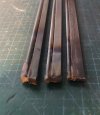
One interesting detail is the radius between the body floor and the walls. The kit comes with a preetched pattern at the inside of the radius to help forming the correct radius of 2mm. I can't imagine how this can be done without a former, so I got a couple of steel profiles and silver soldered them together to form a bending jig.

I made them for 1.5mm, 2mm and 2.5mm, to avoid any surprise.

IMG_20221103_184000_cut_sml.jpg

I can't show a decent picture of the bending, only a snapshot. The whole body was placed on a flat piece of aluminium, the jigs positioned and everything clamped down. I am very happy with the result. The curvature is even all along the body. Only the cutouts needed some rework.

IMG_20221015_203413_cut_sml.jpg

The kit is a piece of art, it has some very nice details like the radiator shutters.
That was a very nice Sunday morning job, made up of four layers each.

IMG_20221023_173830_cut_sml.jpg

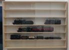
I did also notice that my loco storage damaged the painting. All locos were sitting on their sides, because the drawers didn't allow them to be stored upright. So I got a nice show case from a local cabinetmaker and now I can present all my models.
No complaints please, I know that it is a crude mixture. :oops:

IMG_20221103_171846_sut_sml.jpg


Michael
 

Brian McKenzie

Western Thunderer
. . . . . so I got a couple of steel profiles and silver soldered them together to form a bending jig.
I made them for 1.5mm, 2mm and 2.5mm, to avoid any surprise.

Michael
It was thanks to another of Michael's threads that prompted me to make a similar bending jig. :thumbs:

Initially, for the 45degree 'shoulder' folds on the first side, it was used set up in a flypress. But then those new folds obstructed press access for the opposing side - without goosenecking the way the blade attached to the press.

So, quick and dirty. :eek: The sledgehammer was tapped down on the rusty steel bar where the arrows show. :)
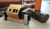
IMG_3781b_Cab folds.jpg

The blade (with 3/16" silver steel rod soldered along lower edge) slides down between pairs of vertical posts (20mm square steel). This presses into a pair of 1/8" bronze brazing rods below. The bend radius provided was sharper than required, and this was eased by placing some rubber sheet on top of the lower bars.

-Brian McK.
 

adrian

Flying Squad
one hit and you're done.

Fixed the problem or destroyed the object.
Often it's the best way, especially folding metal. Too often you see people trying to coax something into shape slowly, the problem is that the metal will work harden. Double and triple check the alignment but then for cabs and fireboxes etc you are better doing it in one decisive go. That said I've never resorted to the sledgehammer!
 

Brian McKenzie

Western Thunderer
The sledgehammer might look a bit dramatic, but there's nothing scary or uncontrolled about the process. :)
There's been too much work in pressing out the window frames, punching rivets and engraving the door apertures to risk it all.

The holes along the edges engage with jig guide pins for those processes, and are in sacrificial areas that get removed later.

Strips of brass, with machined markings, are temporarily soldered either side to indicate fold locations.

Cab fold sacrificial guide strips_3761x.jpg
 

michael080

Western Thunderer
this picture gave me a bit of a headache.

IMG_20221113_170859_sml_cr.jpg

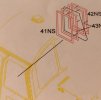
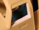
How can I assemble 2 * 2 flimsy nickel silver frames, glue a piece of clear plastic in between and bend the upper edge of the sandwich to fit in the resin cabin?

Taking a close look at prototype pictures revealed that the upper end of the windows were not bent, the main part of the window could be opened and the whole window is in one plane.

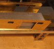
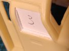
I had to create straight planes in the resin cabins with evergreen profiles so that the windows can fit properly.


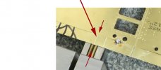
IMG_20221113_170921_cr.jpg


and this is how the glass will sit in the window.

IMG_20221113_170915_cr.jpg

I am still waiting for the gear boxes. It appears that they were sent and German customs rejected the parcel and returned it to Finney7. :shit:

have a nice week!

Michael
 
Top