7mm Mickoo's Commercial Workbench

mickoo

Western Thunderer
Mick,

What adhesive do you favour for gluing the 3d prints to metal particularly the slidebars to the cylinders?

atb
Tim
Tim, usually Loctite 480 or Devcon 5 Min epoxy, but never flat surface to flat surface as I find they pop off after a while, I always add a secondary fixing, something that protrudes from the brass and fits into a socket in the resin or vice versa. The adhesive bonds better if it can grab two surfaces at different angles, 90° is good.

The sand boxes are hollow on their back, soldered to the frames is a hoop of 0.6 mm wire that sits inside that hollow, the hollow is filled with Devcon and placed over the hoop and positioned in it's final place, the Devcon gloops down and around the hoop and bonds the two together.

The cylinder blocks have holes in the rear into which two 6BA threaded rods are inserted and secured with Devcon, the thread gives it extra grip; I've tried with smooth rods and if you give it a twist, it'll pull right out. The studs pass through the frames and are held in place with nuts on the inside.

The motion bracket will be soldered to the frames, the slide bars are soldered to the motion bracket, at the front end of the slide bar a tang fits into a slot in the cylinder block. Both parts are respectively secured to the frames so there is no need to bond the two together, their loading is taken up at other points. As a double fixing I may add 480 to the tangs when I finally fix the cylinders in place.
 

mickoo

Western Thunderer
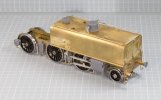
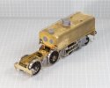
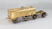
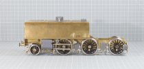
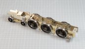
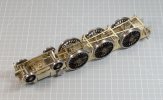
Just the valve gear to add and the front engine will be pretty much done.

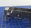
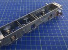
Extras are all Laurie Griffin, cast lamp irons, steam sanding traps and pipework and two port oil pot on RH side of water tank. The steam sanding traps are cast integral with the pipe and coupling for the steam line, however, they coupling is too close to the trap for the Garratt. You need to cut the pipe off, drill the trap then refit the pipe backward so the coupling is closer to the wheel.

I didn't fit the trap to the inside leading sand box, you can barely see it and it impinges on the pony side control; the pipework is also not long enough so I simply added a new pipe and coupling directly into the bottom of the sand box.

I do need to add the main exhaust pipe where it sweeps down under the intermediate axle and couples to the engine, but that'll be fabricated once all the boiler bed plate section is complete.

IMG_10737.jpg

IMG_10738.jpg

IMG_10739.jpg

IMG_10740.jpg
 

mickoo

Western Thunderer
Tim,

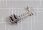
I had to revise the cylinder and motion bracket set up, I couldn't get the Slaters wheels off the axle to fit the motor, I could have made the axle drop out the bottom but then the kit is designed to be fixed and I'd also have to make the brake gear removable, I opted for neither.

Anyway the motion bracket has an extra 12BA stud fitted near the top, outside of the frames I filed it square.

You can barely see up under there, but if you did look, then it'll appear more like a square bracket than a 12BA bit of stud.

IMG_10745.jpg

IMG_10749.jpg

IMG_10747.jpg

The valve slide block casting is a 3D print fitted to the bottom of the footplate and it drops down over the assembled valve gear, it's held in place with 12BA bolts but once I'm happy the part fits over the valve gear then I'll add some adhesive to bond it better to the footplate.

IMG_10743.jpg

IMG_10744.jpg
 

Rob R

Western Thunderer
Apart from leaving the solder filter off the camera you're starting to get quite good at this loco building lark aren't you:)
 

mickoo

Western Thunderer
Apart from leaving the solder filter off the camera you're starting to get quite good at this loco building lark aren't you:)
Ran out of brass solder mate :rant:had to use the commoner silver stuff :rolleyes:
Quite good? I'd like to think so, it puts bread on the table and beer in the fridge, figuratively speaking.

Once the new Bat cave, should really call it a bunker, is done then, I'll be able to stream line the work flow, spread tools and the bigger machinery about, right now everything is all a bit cramped. I had to laugh at the 3D print thread about space needed, I do all mine in a rough 700x400 space and the printer takes up 400x400 :eek:
 

Tim Humphreys ex Mudhen

Western Thunderer
Tim,

I had to revise the cylinder and motion bracket set up, I couldn't get the Slaters wheels off the axle to fit the motor, I could have made the axle drop out the bottom but then the kit is designed to be fixed and I'd also have to make the brake gear removable, I opted for neither.

Anyway the motion bracket has an extra 12BA stud fitted near the top, outside of the frames I filed it square.

You can barely see up under there, but if you did look, then it'll appear more like a square bracket than a 12BA bit of stud.

View attachment 155133

View attachment 155135

View attachment 155134

The valve slide block casting is a 3D print fitted to the bottom of the footplate and it drops down over the assembled valve gear, it's held in place with 12BA bolts but once I'm happy the part fits over the valve gear then I'll add some adhesive to bond it better to the footplate.

View attachment 155131

View attachment 155132

Nice solution Mick,

atb
Tim
 

Silverystreaks

Western Thunderer
Mick
The steam sanding traps and pipework you mention from Laurie Griffin. Could not find them on his website.

They have always been a pain to replicate from scratch so it would be a boon if they were available as castings
Regards
Bob
 

mickoo

Western Thunderer
Mick
The steam sanding traps and pipework you mention from Laurie Griffin. Could not find them on his website.

They have always been a pain to replicate from scratch so it would be a boon if they were available as castings
Regards
Bob
Steam sanding pipes 25-007 pk 6


I cut the double flanges off the top and used the remaining spigot into the bottom of the sand box. They may not be perfect LMS copies but they're close enough.

I think the actual trap in 1:1 was a common 3rd part (like injectors etc) component and sourced by several builders and fitted to many different engines over the years.

Hope that helps.
 

Silverystreaks

Western Thunderer
Steam sanding pipes 25-007 pk 6


I cut the double flanges off the top and used the remaining spigot into the bottom of the sand box. They may not be perfect LMS copies but they're close enough.

I think the actual trap in 1:1 was a common 3rd part (like injectors etc) component and sourced by several builders and fitted to many different engines over the years.

Hope that helps.
Much appreciated Mick and Paul.... I need to have my eyes tested
Kindest regards
Bob
 

mickoo

Western Thunderer
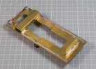
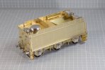
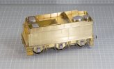
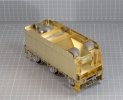
Just about there with the Finney7 4000G tender for the Hall build.

The sloped coal space is just held in with tape; I still need to get in under there when the correct tank vents arrive, I need the oblong style ones, the kit came with the mushroom topped pipe type...an oversight in the packing dept :eek:...since rectified :thumbs:

The rear corner handrails will get fitted once I have dressed the flared corners, I need to throw a witness layer of paint on there first to help see where it needs smoothing out.

The final model will have a full load of coal so anything covered by coal is....well, quite frankly, a mess ; since it cannot be seen there's little point cleaning it up or taking due care to keep it neat.

IMG_0750.jpg

IMG_0751.jpg

IMG_0752.jpg
 

mickoo

Western Thunderer
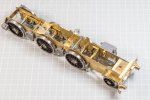
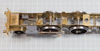
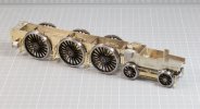
Finney7 Hall chassis all done, the sand pipes will go in after paint as they can be a bit fragile and bend about a bit.

Nothing untoward here, just follow the yellow brick road, paint by numbers sort of thing. This is an out of the box build so no extras, though I might add a 3D brake cylinder in there to give the area a bit more mass, it'll have to be notched to fit around the stay for the front axle rocking arm though.

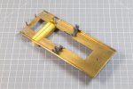
The tab slots under the cylinders will be covered by the cylinders themselves, but the two over the leading pony wheel are fully exposed. Why there isn't a little detail overlay here is strange, perhaps something to consider upgrading long term.

Short term (for this build) I might just add a thin cover sheet here once the cylinders are in place, then I can get a reference point to butt up to.

Upper works start tomorrow, hopefully it'll all be done and ready for paint by months end :thumbs:

IMG_10755.jpg

IMG_10756.jpg

IMG_10757.jpg
 

7mmMick

Western Thunderer
Lovely job pal. The Finney Hall really does fall together but like you could do with an upgrade as the level of detail isn’t at the same level as the Duchess and West Country. I added the injectors to the frames as especially the exhaust injector sits right under the frames. I knocked up a couple of brackets from scrap etch if I remember? Also the bogie definitely needs a vertical spring to keep it in positive contact with the rail,CA123CD9-A884-4146-AD86-3F42E43D5313.jpeg
2D7956CA-B785-43B3-9C5F-4730B25C3251.jpeg
 

mickoo

Western Thunderer
That's interesting, your sand boxes look a different shape and fitted directly to the frames, mine are much further out so that the cap is in line with where the step support plate will go. Comparing with photos and hindsight, I may have to move them up a few mm but will wait until I have the step positions as a reference to go from, if they have to go too far then I'll have to extend the bracket as well.

The injector does appear to be mounted lower and further to the rear on the late examples I've looked at; such that the rear vertical pipe is behind the stay. I've got two fold over tabs at the top of the frame which I am going to assume holds that rear vertical pipe. I'll add extra parts to hold the front pipes though once the cab is in place so I can mark them up. :thumbs:
 

Dave Holt

Western Thunderer
I imagine there should be a substantial bracket from the frames to support the injector body (and exhaust injector), or is the live steam injector mounted from the cab steps? Injectors definitely don't hang from the pipework.
Dave.
 

7mmMick

Western Thunderer
That's interesting, your sand boxes look a different shape and fitted directly to the frames, mine are much further out so that the cap is in line with where the step support plate will go. Comparing with photos and hindsight, I may have to move them up a few mm but will wait until I have the step positions as a reference to go from, if they have to go too far then I'll have to extend the bracket as well.

The injector does appear to be mounted lower and further to the rear on the late examples I've looked at; such that the rear vertical pipe is behind the stay. I've got two fold over tabs at the top of the frame which I am going to assume holds that rear vertical pipe. I'll add extra parts to hold the front pipes though once the cab is in place so I can mark them up. :thumbs:
I’m not 100% my sandbox mounting is right to be honest. The instructions weren’t mega clear and I struggled to find prototype info. The injector pipe runs are best guess without a drawing to work from
 
Top