You are using an out of date browser. It may not display this or other websites correctly.
You should upgrade or use an alternative browser.
You should upgrade or use an alternative browser.
2mm Modbury
- Thread starter Ian Smith
- Start date
Ian Smith
Western Thunderer
Allen,Thanks for the film.
I assume, from the wide range of company wagons that the train was taken to a yard somewhere (Peterborough?) then broken up and sent to their respective area.
Regards
Allen
The film dates from the early 1920’s, so post wagon pooling. So the train almost certainly would not have been split up to be sent to different regions of the country, I assume that the train would comprise of any wagons suitable for the load that were available locally.
Ian
Ian Smith
Western Thunderer
Not really for Modbury this time...
Tomorrow, myself and 3 other members of the Midland Area Group are going up to the North Mercia Area Group meeting (one of our number is giving a little talk on Tank Wagons) and hopefully we'll get to see the progress Laurie is making with Yeovil. With this visit in mind, a couple of weeks ago I decided that it would be rude not to provide a little something for Laurie to add to his magnum opus.
I therefore began trying to make a few trees to hopefully add a little colour to his bare baseboards. It was my intention to make about half a dozen or so but in the end only 3 have been completed.
The basis this time has been 0.4mm florists wire (in the past I have always used copper wire so this is new to me, although back in the dim and distant I used to use Bowden cable for 4mm trees). I picked up a small spool of about 50 meters (I think) for £3-£4 from a local garden centre, and set to cutting lengths off and twisting them together to form a basic tree-shaped armature.

Once the bundle looked vaguely tree-like, I dribbled runny superglue into it to secure the twists as good as possible. Once dry, I mixed PVA, Polyfilla with a little black acrylic paint and an even smaller amount of sap green acrylic to make a sticky mess that I could paint over the armature to cover the twists of wire. 2 or 3 coats were necessary to cover the twists in the wire. As an aside, I always mix this in a small jam jar, the type you get when you order a cream tea, as the screw on lid will prevent the mix drying out for a surprisingly long period!
Once thoroughly dry, I discovered that the bark colouring wasn't quite what I had in mind, so ended up mixing up a grey-brown colour which was sloshed over everything to give me a bark colour that I was happy with! The benefit of my colouring failure is that should the covering chip or crack at any point in the future that at least it won't be a stark white!
For this deciduous tree (it was meant to be an Elm), the foliage was built up from small clumps of Woodland Scenics Polyfibre, small pieces about the size of a thumb nail were cut from the mat and teased out to something twice or more in size. These pieces were then sprayed with matt lacquer (from Halfords), then dragged through a pile of flock scenic material of an Olive green colour. The loose material was shaken off and the pieces put to one side to harden. It was then a simple matter of selecting suitable pieces and securing them to the ends of the branches of the armature. The finished "Elm" can be seen below.

The other trees forming this "gift" are a pair of Scot's Pine. The basic armature was formed in the same way as the elm, but obviously formed to resemble the outline of a Scot's Pine. The bark covering received the same treatment as the previous tree, but once dry the upper reaches of the tree's trunk and branches were dry-brushed with an orangey-red to better emulate the colouring that a Scot's Pine displays.
The foliage of these trees was this time formed from Woodland Scenics foliage mat, their "Dark Green", although my bag of this is probably the best part of 30 odd years old so may not be the same hue as their current product as green is notoriously prone to fading! Pieces of the mat were cut/torn away, then teased out slightly before being sprayed with the acrylic lacquer - I did this mainly in the hope that it would seal the material and so prevent bits of greenery dropping off the underlying mat. I'm not really sure that it was a good idea as the process has "flattened" the material, perhaps I overdid the lacquer application.
However, I'm reasonably happy with the "form" of these two and to my mind at least they look like what they are meant to represent :

I hope that Laurie will be happy with them and will find a space on Yeovil for them.
Thanks for looking.
Ian
Edit : I forgot to mention that these trees are 2mm scale, the shortest of the Scot's Pine is 150mm tall (75'), the other Scot's Pine and the Elm are just a little taller at about a scale 80'.
Tomorrow, myself and 3 other members of the Midland Area Group are going up to the North Mercia Area Group meeting (one of our number is giving a little talk on Tank Wagons) and hopefully we'll get to see the progress Laurie is making with Yeovil. With this visit in mind, a couple of weeks ago I decided that it would be rude not to provide a little something for Laurie to add to his magnum opus.
I therefore began trying to make a few trees to hopefully add a little colour to his bare baseboards. It was my intention to make about half a dozen or so but in the end only 3 have been completed.
The basis this time has been 0.4mm florists wire (in the past I have always used copper wire so this is new to me, although back in the dim and distant I used to use Bowden cable for 4mm trees). I picked up a small spool of about 50 meters (I think) for £3-£4 from a local garden centre, and set to cutting lengths off and twisting them together to form a basic tree-shaped armature.
Once the bundle looked vaguely tree-like, I dribbled runny superglue into it to secure the twists as good as possible. Once dry, I mixed PVA, Polyfilla with a little black acrylic paint and an even smaller amount of sap green acrylic to make a sticky mess that I could paint over the armature to cover the twists of wire. 2 or 3 coats were necessary to cover the twists in the wire. As an aside, I always mix this in a small jam jar, the type you get when you order a cream tea, as the screw on lid will prevent the mix drying out for a surprisingly long period!
Once thoroughly dry, I discovered that the bark colouring wasn't quite what I had in mind, so ended up mixing up a grey-brown colour which was sloshed over everything to give me a bark colour that I was happy with! The benefit of my colouring failure is that should the covering chip or crack at any point in the future that at least it won't be a stark white!
For this deciduous tree (it was meant to be an Elm), the foliage was built up from small clumps of Woodland Scenics Polyfibre, small pieces about the size of a thumb nail were cut from the mat and teased out to something twice or more in size. These pieces were then sprayed with matt lacquer (from Halfords), then dragged through a pile of flock scenic material of an Olive green colour. The loose material was shaken off and the pieces put to one side to harden. It was then a simple matter of selecting suitable pieces and securing them to the ends of the branches of the armature. The finished "Elm" can be seen below.
The other trees forming this "gift" are a pair of Scot's Pine. The basic armature was formed in the same way as the elm, but obviously formed to resemble the outline of a Scot's Pine. The bark covering received the same treatment as the previous tree, but once dry the upper reaches of the tree's trunk and branches were dry-brushed with an orangey-red to better emulate the colouring that a Scot's Pine displays.
The foliage of these trees was this time formed from Woodland Scenics foliage mat, their "Dark Green", although my bag of this is probably the best part of 30 odd years old so may not be the same hue as their current product as green is notoriously prone to fading! Pieces of the mat were cut/torn away, then teased out slightly before being sprayed with the acrylic lacquer - I did this mainly in the hope that it would seal the material and so prevent bits of greenery dropping off the underlying mat. I'm not really sure that it was a good idea as the process has "flattened" the material, perhaps I overdid the lacquer application.
However, I'm reasonably happy with the "form" of these two and to my mind at least they look like what they are meant to represent :
I hope that Laurie will be happy with them and will find a space on Yeovil for them.
Thanks for looking.
Ian
Edit : I forgot to mention that these trees are 2mm scale, the shortest of the Scot's Pine is 150mm tall (75'), the other Scot's Pine and the Elm are just a little taller at about a scale 80'.
Renovater
Western Thunderer
Your trees reminded me of this thread, for those who model in this scale, incredible, 40 odd pages. RE: Modellbau im M 1:160 - 38
same thread RE: Modellbau im M 1:160 - 19
same thread RE: Modellbau im M 1:160 - 19
Last edited:
Ian Smith
Western Thunderer
With the latest edition of MRJ (No. 288), Modbury has finally made it into print. Only a subset of the photos sent in were used in the article, so below are some of the ones that have been left on the cutting room floor :

The layout plan.

'Buffalo' class No.1601 departing Modbury with a local passenger train of 6 wheeled coaches.
 A view of the goods yard at a quiet moment.

'Buffalo' class No. 1601 carrying ordinary (pick-up) goods K headcode continues its journey towards Newton Abbot.

Dean Goods No. 2569 deposits a couple of loaded wagons from the mornings ordinary (pick-up) goods into the Goods Shed siding at Modbury.
There were a few other photos that didn't make the cut too, as I submitted a selection of about 20 for possible inclusion in the article. All of the photos were taken by me, and most of them had a degree of "photo stacking" to try to improve the depth of field. The photo stacking was done manually, taking 3 or 4 images at different focal lengths, then using GIMP to clone the in-focus areas of each image to form the final photo. Although I was happy with the outcome, there were places in the final images that had to be "manipulated" slightly as the different focal length images didn't always (very rarely) line up correctly.
Thanks for looking,
Ian
The layout plan.
'Buffalo' class No.1601 departing Modbury with a local passenger train of 6 wheeled coaches.
A view of the goods yard at a quiet moment.'Buffalo' class No. 1601 carrying ordinary (pick-up) goods K headcode continues its journey towards Newton Abbot.
Dean Goods No. 2569 deposits a couple of loaded wagons from the mornings ordinary (pick-up) goods into the Goods Shed siding at Modbury.
There were a few other photos that didn't make the cut too, as I submitted a selection of about 20 for possible inclusion in the article. All of the photos were taken by me, and most of them had a degree of "photo stacking" to try to improve the depth of field. The photo stacking was done manually, taking 3 or 4 images at different focal lengths, then using GIMP to clone the in-focus areas of each image to form the final photo. Although I was happy with the outcome, there were places in the final images that had to be "manipulated" slightly as the different focal length images didn't always (very rarely) line up correctly.
Thanks for looking,
Ian
Ian Smith
Western Thunderer
Ade, Geoff,I can only echo what Geoff says, wizards indeed. I don’t remember seeing any photos of the RH FY scene break? Not got my copy with me right now.
Cheers
Thank you for the kind comments (and to everyone else for the “likes”).
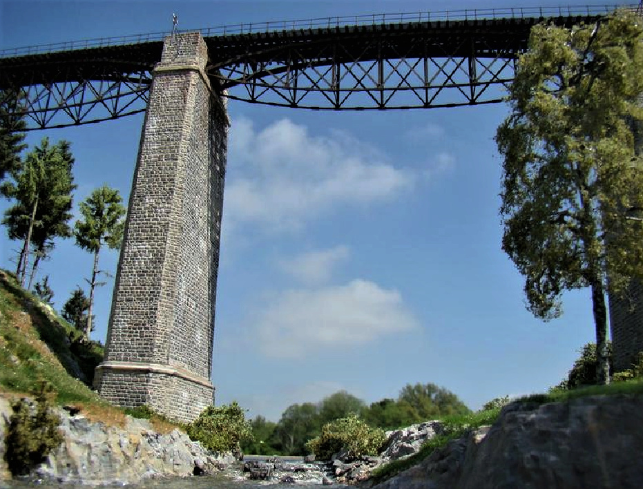
The header photo is the nearest any of the photos get to the mouse hole on the right hand end of the scene. The hole is at the end of the embankment a few inches beyond the signals, so is (only) partially disguised by an elm tree in a field boundary near the foot of the embankment.
Ian
Joe's Garage
Western Thunderer
Hi Ian, your modelling skills are really remarkable considering the scale you work in, very inspirational. If I could model in 2 mm my dream layout of Abbotsbury (1912 to mid WW1) would be possible considering the space I have at present. Your models of the 517 and steam rail motor are beautiful examples.
On a slightly different note I was looking at your blog, very informative, especially the signal box as it looks similar to the original at Abbottsbury. But as always you get distracted by the links! What caught my eye was Julia Andrews' Highclere layout and her comments of disposal.....is it still in existence or has it moved on? Yes the DNSR is another interest of mine. I sometimes imagine what it may have become if it was kept open? Interesting speculation for a model.
All the best
Julian
Ian Smith
Western Thunderer
Julian,Hi Ian, your modelling skills are really remarkable considering the scale you work in, very inspirational. If I could model in 2 mm my dream layout of Abbotsbury (1912 to mid WW1) would be possible considering the space I have at present. Your models of the 517 and steam rail motor are beautiful examples.
On a slightly different note I was looking at your blog, very informative, especially the signal box as it looks similar to the original at Abbottsbury. But as always you get distracted by the links! What caught my eye was Julia Andrews' Highclere layout and her comments of disposal.....is it still in existence or has it moved on? Yes the DNSR is another interest of mine. I sometimes imagine what it may have become if it was kept open? Interesting speculation for a model.
All the best
Julian
Thank you for your kind comments!
I’m currently picking up the steam railmotor again as I’m trying to sort out the Walschearts valve gear - I hope to get it finished for the 2mm Association 60+2 year anniversary bash in Derby in June.
With regards to Julia’s Highclere layout, I have no idea about it. I don’t think she’s updated her blog for some time. If she has an email link on her blog you could try dropping her a line.
Ian
Joe's Garage
Western Thunderer
As I said Ian 2 mm modelling is a very fine art....hmmm Walschearts valve gear! Hopefully someone will take some video of the anniversary.
All the best
Julian
All the best
Julian
Ian Smith
Western Thunderer
As mentioned above, after a few months of prevarication I have once again picked up the Steam Railmotor project with a view to trying to produce the Walschaerts valve gear for it 
As is my wont, I am very much playing this by ear and have no documented plan of how I'm actually going to do all of this, but at least I've made a start!!
The first element were the connecting rods and crossheads. I was originally going to fabricate these from some milled nickel silver strip, but luckily I discovered that N Brass do a little kit of parts for N gauge crossheads which comprise a cast brass back for the crosshead (which is a flattened T profile) and has a relevant rebate formed in it for the end of the connecting rod, some etched crosshead fronts (of slightly different designs/sizes), and a bit of straight nickel silver wire for the piston shaft. Before starting on the little kit though, I first produced the connecting rods from a pair of generic 14.5mm coupling rods. The boss was filed away at one end and the coupling rod tapered by careful filing. Once I was happy that the little end of the rods would fit (and had room to move) within the cast part of the N Brass crosshead assembly, the crosshead assembly was constructed. This involved drilling out a little hole to accommodate the piston shaft in one end of the cast part of the crosshead, then sweating on the etched face of the crosshead - to do this I chemically blackened the shaft of a 0.45mm drill and mounted the cast and etched parts around it before introducing the hot iron (the blackening ensured that I didn't solder the drill into the assembly!!) With those parts joined, the little end of the connecting rod (after it too was chemically blackened) was introduced and a stub of wire soldered from and rear of the crosshead. The photo below shows the result :

The next step was to produce the cylinders. I elected to file these from solid brass, and the plan is to eventually "araldite" them in place on the chassis, to aid location, a couple of pegs are soldered in them which engage in corresponding holes in the ends of the chassis. The photos below hopefully illustrate :


As can be seen, I ended up having to widen the original cylinders with patches of nickel silver strip to give me the necessary clearance - the patches were silver-soldered on and the mounting pegs re-made.
The next step was to produce the motion bracket and slide bars. Initially, I intended to make these in steel (for strength), so fretted and filed a suitable shape :
.JPG")
Although in the end as my ideas developed, I ended up making some new ones in 0.018" nickel silver strip, partly because the steel was a little bit too thick for the crosshead slots. The revised motion bracket / slide bar assemblies can be seen below :

As can be seen once formed, the motion bracket was folded back at 90 degrees, and the back edge of the bracket has a little tab sticking out which engages in a slot filed in the top of the chassis. The image below shows one of the brackets hanging in its slot in the chassis :

The final element of progress so far is a pair of turnings for the cylinder blocks, these will be notched top and bottom (one already has been) to accommodate the ends of the slide bars:

The idea being that the slide bars will be soldered into these turnings which in turn go inside the large holes in the cylinders. However before I go that far there are various holes that need to be drilled near the motion bracket for the quadrant and reversing lever pivot thing.
Thanks for looking.
Ian
Edited to add the photo of the cylinder turnings in the cylinder block.
As is my wont, I am very much playing this by ear and have no documented plan of how I'm actually going to do all of this, but at least I've made a start!!
The first element were the connecting rods and crossheads. I was originally going to fabricate these from some milled nickel silver strip, but luckily I discovered that N Brass do a little kit of parts for N gauge crossheads which comprise a cast brass back for the crosshead (which is a flattened T profile) and has a relevant rebate formed in it for the end of the connecting rod, some etched crosshead fronts (of slightly different designs/sizes), and a bit of straight nickel silver wire for the piston shaft. Before starting on the little kit though, I first produced the connecting rods from a pair of generic 14.5mm coupling rods. The boss was filed away at one end and the coupling rod tapered by careful filing. Once I was happy that the little end of the rods would fit (and had room to move) within the cast part of the N Brass crosshead assembly, the crosshead assembly was constructed. This involved drilling out a little hole to accommodate the piston shaft in one end of the cast part of the crosshead, then sweating on the etched face of the crosshead - to do this I chemically blackened the shaft of a 0.45mm drill and mounted the cast and etched parts around it before introducing the hot iron (the blackening ensured that I didn't solder the drill into the assembly!!) With those parts joined, the little end of the connecting rod (after it too was chemically blackened) was introduced and a stub of wire soldered from and rear of the crosshead. The photo below shows the result :
The next step was to produce the cylinders. I elected to file these from solid brass, and the plan is to eventually "araldite" them in place on the chassis, to aid location, a couple of pegs are soldered in them which engage in corresponding holes in the ends of the chassis. The photos below hopefully illustrate :
As can be seen, I ended up having to widen the original cylinders with patches of nickel silver strip to give me the necessary clearance - the patches were silver-soldered on and the mounting pegs re-made.
The next step was to produce the motion bracket and slide bars. Initially, I intended to make these in steel (for strength), so fretted and filed a suitable shape :
Although in the end as my ideas developed, I ended up making some new ones in 0.018" nickel silver strip, partly because the steel was a little bit too thick for the crosshead slots. The revised motion bracket / slide bar assemblies can be seen below :
As can be seen once formed, the motion bracket was folded back at 90 degrees, and the back edge of the bracket has a little tab sticking out which engages in a slot filed in the top of the chassis. The image below shows one of the brackets hanging in its slot in the chassis :
The final element of progress so far is a pair of turnings for the cylinder blocks, these will be notched top and bottom (one already has been) to accommodate the ends of the slide bars:
The idea being that the slide bars will be soldered into these turnings which in turn go inside the large holes in the cylinders. However before I go that far there are various holes that need to be drilled near the motion bracket for the quadrant and reversing lever pivot thing.
Thanks for looking.
Ian
Edited to add the photo of the cylinder turnings in the cylinder block.
Last edited:
Ian Smith
Western Thunderer
A little more progress (I hope) on the motion for the Steam Railmotor...
First a diagram of what I'm going to try to achieve (which will also help me to remember what some of the various linkages are called) :

So, since the last instalment, the Motion Bracket / Slide Bar components have had the temporary bridging pieces removed from the ends of the slide bars, and the "cylinder end" turnings soldered on in their stead :


One side of the motion bits just hanging on the side of the chassis.
With the "cylinder end" turnings in place, it became obvious that I hadn't really got enough land on the cylinder above the top slide bar for the valve stem (especially as I'm probably having to make all of this a little overscale). Therefore the cylinders were increased in size by soldering pads of 0.018" nickel silver onto the top, and I also took the opportunity to add strips of 0.010" along the top edge of the cylinders to represent the bulbous nature of the real thing at this point. The excess around the cylinder being filed back flush afterwards.
The photo below shows the various bits made so far :

Hopefully, the slight increase in size of the cylinders can be seen complete with the bulbous extension the outside face. As can be seen, I've started making a few motion pins (one of which is posed in one of the union links). The scrap of 2 laminated pieces of 0.010" in the middle has had some holes drilled in it ready to fret/file out a pair of combination levers. The lower motion bracket / slide bar component has had a valve stem guide and valve stem soldered o, and just to the right and below is a very tiny little piece that will move along the valve stem and be connected to the upper end of the combination lever!
Finally, a photo of the RHS bits hanging in place on the chassis :

I really don't know how do-able all this is going to be, as I'm literally playing by ear as I progress, and because of the overscale size of some of the components it may not actually physically work!! However, if I end up with something that waggles about and looks busy then I'll be more than happy!
Thanks for looking.
Ian
First a diagram of what I'm going to try to achieve (which will also help me to remember what some of the various linkages are called) :
So, since the last instalment, the Motion Bracket / Slide Bar components have had the temporary bridging pieces removed from the ends of the slide bars, and the "cylinder end" turnings soldered on in their stead :
One side of the motion bits just hanging on the side of the chassis.
With the "cylinder end" turnings in place, it became obvious that I hadn't really got enough land on the cylinder above the top slide bar for the valve stem (especially as I'm probably having to make all of this a little overscale). Therefore the cylinders were increased in size by soldering pads of 0.018" nickel silver onto the top, and I also took the opportunity to add strips of 0.010" along the top edge of the cylinders to represent the bulbous nature of the real thing at this point. The excess around the cylinder being filed back flush afterwards.
The photo below shows the various bits made so far :
Hopefully, the slight increase in size of the cylinders can be seen complete with the bulbous extension the outside face. As can be seen, I've started making a few motion pins (one of which is posed in one of the union links). The scrap of 2 laminated pieces of 0.010" in the middle has had some holes drilled in it ready to fret/file out a pair of combination levers. The lower motion bracket / slide bar component has had a valve stem guide and valve stem soldered o, and just to the right and below is a very tiny little piece that will move along the valve stem and be connected to the upper end of the combination lever!
Finally, a photo of the RHS bits hanging in place on the chassis :
I really don't know how do-able all this is going to be, as I'm literally playing by ear as I progress, and because of the overscale size of some of the components it may not actually physically work!! However, if I end up with something that waggles about and looks busy then I'll be more than happy!
Thanks for looking.
Ian
Joe's Garage
Western Thunderer
Im very much in the dirty camp, good weathering brings a model to life. I’m to young to remember steam so I go by colour photography and even clean locos had some dirt about them.
That already looks phenomenal (at roughly 4 times life size on my screen). Chapeau!
Adam
Hi Ian
As Adam says ....It just seems remarkable considering that this is in 2mm!
Would you be tempted to make another?!
All the best
Julian
Grahame Hedges
Western Thunderer
Amazingly intricate fine-scale workmanship.
Ian Smith
Western Thunderer
A little more progress on the Steam Railmotor ...
Most of the motion has now been completed on the RHS of the drive unit. Obviously, much of this is slightly over scale as in 2mm scale this stuff is flipping minute!! Effectively, each of the links has been drilled and cut to size based on what looks and works, rather than a scale version based on any drawings available. The main reason for this is the amount of throw provided by the generic 7.5mm wheel set available from the 2mm Association - I think that the scaled down crank throw of the prototype is somewhat smaller than that provided by the wheel sets used. This means that the for and aft movement of the crossheads in the slide bars is greater than it should be for example.
However, I am perfectly willing to accept such compromises so long as it fulfils my requirements of "waggling about and looking busy". This is after all a layout model not a museum piece!!
For future reference, the various linkages have had their pivot holes at the following centres :
Union Link - 2.5mm
Combination Lever - 3.5mm + 1.5mm
Radius Bar - 4.5mm +1.5mm
(These were the sizes that I eventually settled on as I had to make 2 of both the Combination Lever and Radius Bar as the originals were either slightly too long or short to provide the movement that worked smoothly).
The photo below shows the motion as it is at the minute - I have still got to make the Return Crank and the Return (or Eccentric) Rod :

At the bottom of the image are 3 failed attempts at making the Quadrant, the one for the LHS motion lies slightly above these 3. As can be seen the one for the RHS motion is in place and free to rock about a central pivot hole. For simplicities sake (and my own sanity), the rear end of the Radius Rod shares this pivot point.
The Union Link, Combination Lever and Radius Bar were pinned together at their respective junctions with small pins made from 0.6mm nickel silver wire - a short stub of wire was left projecting from the chuck of a mini drill, and a fine file used to reduce the wire until it fitted in the holes drilled in the various linkages. The chuck was released, wire pulled out a about a mm, chuck tightened and a fine piercing saw employed to cut off the wire against the chuck jaw. The resulting pin was popped in a pin vice and the head of the pin filed down to leave a little motion pin. The pins were placed in the relevant hole, a piece of cigarette paper used as a barrier, the other rod slipped on, and a flash of solder applied before the excess pin was filed back flush (or nearly so) with the rear of the linkage.
For the Quadrant and rear Radius Rod pivot, a 0.4mm hole was drilled through the bit of meat that I'd left for this pivot hole on the bent up motion bracket slide bars. For the outer bracket of this pivot point, a small piece of 0.018" nickel silver was cut and bent (having had what will be the front face thinned to about 0.010") and soldered in place suitably spaced from the slide bars by a piece of paxolin. Once in place, the previously drilled hole was used to sight the drill so that the pivot point could pass through both front bracket and rear. Then an enjoyable few minutes ensued where I tried to line up all the bits and pass another pivot pin through. Once happy, a flash of solder was applied to the rear of the pivot pin, and satisfied that I hadn't soldered it solid the same was done at the front supporting bracket (again checking that everything was still free to move!)
The reversing rod and crank were bent up from a single piece of wire that passed through the middle hole in the Radius Rod, and the crank pivot point drilled in the space left for it on the bent up Motion Bracket Slidebars (any one would think that I had actually planned how all of this lot was going to hang together reading this!!) Once happy that the bit of bent wire was the right size and shape, the bit where the crank would be was popped in a vice and squashed flat. A small piece of 0.010" was soldered onto this flat, then filed to a tapered crank shape. As it happened, the wire when inserted into the Radius Rod slightly fouled the very slight movement of the latter, so I elected to snip off the projecting wire just past the bend so that to all intents and purposes (to a casual observer, who's squinting and probably not looking too closely anyway) it appears to connect to the Radius Rod.
A further small turning provides the cylinder front face, and when all these little sub-components are joined up and hung on the chassis it looks like this :
So far I'm pretty happy as it seems to fulfil those criteria of "waggling about and looking busy". As can be seen, I've even managed to get a working valve spindle crosshead (if that's what it's called).
Thank you for looking.
Ian
Most of the motion has now been completed on the RHS of the drive unit. Obviously, much of this is slightly over scale as in 2mm scale this stuff is flipping minute!! Effectively, each of the links has been drilled and cut to size based on what looks and works, rather than a scale version based on any drawings available. The main reason for this is the amount of throw provided by the generic 7.5mm wheel set available from the 2mm Association - I think that the scaled down crank throw of the prototype is somewhat smaller than that provided by the wheel sets used. This means that the for and aft movement of the crossheads in the slide bars is greater than it should be for example.
However, I am perfectly willing to accept such compromises so long as it fulfils my requirements of "waggling about and looking busy". This is after all a layout model not a museum piece!!
For future reference, the various linkages have had their pivot holes at the following centres :
Union Link - 2.5mm
Combination Lever - 3.5mm + 1.5mm
Radius Bar - 4.5mm +1.5mm
(These were the sizes that I eventually settled on as I had to make 2 of both the Combination Lever and Radius Bar as the originals were either slightly too long or short to provide the movement that worked smoothly).
The photo below shows the motion as it is at the minute - I have still got to make the Return Crank and the Return (or Eccentric) Rod :
At the bottom of the image are 3 failed attempts at making the Quadrant, the one for the LHS motion lies slightly above these 3. As can be seen the one for the RHS motion is in place and free to rock about a central pivot hole. For simplicities sake (and my own sanity), the rear end of the Radius Rod shares this pivot point.
The Union Link, Combination Lever and Radius Bar were pinned together at their respective junctions with small pins made from 0.6mm nickel silver wire - a short stub of wire was left projecting from the chuck of a mini drill, and a fine file used to reduce the wire until it fitted in the holes drilled in the various linkages. The chuck was released, wire pulled out a about a mm, chuck tightened and a fine piercing saw employed to cut off the wire against the chuck jaw. The resulting pin was popped in a pin vice and the head of the pin filed down to leave a little motion pin. The pins were placed in the relevant hole, a piece of cigarette paper used as a barrier, the other rod slipped on, and a flash of solder applied before the excess pin was filed back flush (or nearly so) with the rear of the linkage.
For the Quadrant and rear Radius Rod pivot, a 0.4mm hole was drilled through the bit of meat that I'd left for this pivot hole on the bent up motion bracket slide bars. For the outer bracket of this pivot point, a small piece of 0.018" nickel silver was cut and bent (having had what will be the front face thinned to about 0.010") and soldered in place suitably spaced from the slide bars by a piece of paxolin. Once in place, the previously drilled hole was used to sight the drill so that the pivot point could pass through both front bracket and rear. Then an enjoyable few minutes ensued where I tried to line up all the bits and pass another pivot pin through. Once happy, a flash of solder was applied to the rear of the pivot pin, and satisfied that I hadn't soldered it solid the same was done at the front supporting bracket (again checking that everything was still free to move!)
The reversing rod and crank were bent up from a single piece of wire that passed through the middle hole in the Radius Rod, and the crank pivot point drilled in the space left for it on the bent up Motion Bracket Slidebars (any one would think that I had actually planned how all of this lot was going to hang together reading this!!) Once happy that the bit of bent wire was the right size and shape, the bit where the crank would be was popped in a vice and squashed flat. A small piece of 0.010" was soldered onto this flat, then filed to a tapered crank shape. As it happened, the wire when inserted into the Radius Rod slightly fouled the very slight movement of the latter, so I elected to snip off the projecting wire just past the bend so that to all intents and purposes (to a casual observer, who's squinting and probably not looking too closely anyway) it appears to connect to the Radius Rod.
A further small turning provides the cylinder front face, and when all these little sub-components are joined up and hung on the chassis it looks like this :
So far I'm pretty happy as it seems to fulfil those criteria of "waggling about and looking busy". As can be seen, I've even managed to get a working valve spindle crosshead (if that's what it's called).
Thank you for looking.
Ian
Ian Smith
Western Thunderer
Steam Railmotor progress ...
With the RHS motion pretty much complete, a start was made on the return cranks and eccentric rods that connect them to the quadrants. The eccentric rods were simply formed using a couple of spare plain etched coupling rods. The boss on one end was reduced in size slightly, and a hole drilled about 11.5mm from the boss for the little end - the real thing was about 6'6" between hole centres (13mm) but that amount of throw cannot be accommodated on my lash up! The return cranks were fretted to shape and size from a piece of 0.018" nickel silver strip after a a pair of holes were drilled at 1.5mm centres to match the crank throw of the Association's 7.5mm wheels. The crank shape being formed around the holes.

The pair of eccentric rods and the return cranks being hacked from a bit of 0.018" nickel silver.
Once the cranks and exxentric rods were formed more little motion pins were "turned up" from 0.7mm nickel silver wire - I say turned up, in reality the wire was popped into a mini drill and files deployed to thin about 2mm of it down to about 0.4mm before cutting off to leave a 0.7mm diameter head on the top. With the pins made, the eccentrics and cranks were joined and the other (little) end of the eccentric rod pinned to the quadrant.

The assembly after the eccentric rods and return cranks added.
A test fit of the motion on the chassis followed - I had deliberately left the hole in the crank a tight fit on the wheel crank pin to allow me to test run the motion without having to solder everything in place.

The LHS motion plonked in place on the chassis.
Luckily, this dry run showed no obvious errors, so a batch or araldite was mixed up and the piston ends were glued into the cylinder block, which in turn was glued to the side of the chassis whilst the motion bracket was also given a smear of glue and against the chassis side using the notch in the chassis top as a guide. The other side was temporarily plonked in place to allow the whole lot to be trapped in a vice for 24 hours for the glue to dry.
Once dry, the RHS motion was removed and the return crank on the LHS soldered in place after ensuring that the rest of the LHS motion was still able to move freely. With just the RHS motion in place, the gearbox and motor was attached to make sure everything worked under power. Satisfied, another batch of araldite was mixed up and the RHS motion was attached and left in the vice to dry overnight.
Finally, the RHS return crank was soldered in place, the motor and gearbox reattached and the complete assembly test run :
Thank you for looking.
Ian
With the RHS motion pretty much complete, a start was made on the return cranks and eccentric rods that connect them to the quadrants. The eccentric rods were simply formed using a couple of spare plain etched coupling rods. The boss on one end was reduced in size slightly, and a hole drilled about 11.5mm from the boss for the little end - the real thing was about 6'6" between hole centres (13mm) but that amount of throw cannot be accommodated on my lash up! The return cranks were fretted to shape and size from a piece of 0.018" nickel silver strip after a a pair of holes were drilled at 1.5mm centres to match the crank throw of the Association's 7.5mm wheels. The crank shape being formed around the holes.
The pair of eccentric rods and the return cranks being hacked from a bit of 0.018" nickel silver.
Once the cranks and exxentric rods were formed more little motion pins were "turned up" from 0.7mm nickel silver wire - I say turned up, in reality the wire was popped into a mini drill and files deployed to thin about 2mm of it down to about 0.4mm before cutting off to leave a 0.7mm diameter head on the top. With the pins made, the eccentrics and cranks were joined and the other (little) end of the eccentric rod pinned to the quadrant.
The assembly after the eccentric rods and return cranks added.
A test fit of the motion on the chassis followed - I had deliberately left the hole in the crank a tight fit on the wheel crank pin to allow me to test run the motion without having to solder everything in place.
The LHS motion plonked in place on the chassis.
Luckily, this dry run showed no obvious errors, so a batch or araldite was mixed up and the piston ends were glued into the cylinder block, which in turn was glued to the side of the chassis whilst the motion bracket was also given a smear of glue and against the chassis side using the notch in the chassis top as a guide. The other side was temporarily plonked in place to allow the whole lot to be trapped in a vice for 24 hours for the glue to dry.
Once dry, the RHS motion was removed and the return crank on the LHS soldered in place after ensuring that the rest of the LHS motion was still able to move freely. With just the RHS motion in place, the gearbox and motor was attached to make sure everything worked under power. Satisfied, another batch of araldite was mixed up and the RHS motion was attached and left in the vice to dry overnight.
Finally, the RHS return crank was soldered in place, the motor and gearbox reattached and the complete assembly test run :
Thank you for looking.
Ian