MOVING COAL - A Colliery Layout in 0 Gauge

PhilH

Western Thunderer
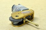
The cab roof requires 6 bolts for which I hadn't allowed half etched dimples, 4 of which were in a line at the rear of the opening hatch cover. Rather than trying to mark these 4 out on the cover I made a template to make the job easier and more accurate.


6 Cab 010B.jpg

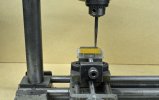
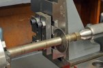
I have one of the early Unimats which has been mainly used with its vertical post as a drilling machine and this has a leadscrew with a fairly accurate metric thread. One turn of the handwheel gives 1mm and its marked with 0.05mm divisions. A piece of scrap brass sheet was bent into an 'L' shape and fixed in the vice and a scriber mounted in the 3 jaw chuck. The scriber was then used to make a series of pop marks in a line with the spacing required on the cover. A couple of extra pop marks were added before and after the required holes corresponding to the edge of the cover plus 0.45mm. The four middle holes were then drilled out to the size required for the pins representing the bolts. The two extra end holes were drilled out 0.9mm and short lengths of 0.9mm brass wire soldered in them, these serve to locate the cover correctly on each side in relation to the bolt holes.


7 Cab 011B.jpg

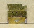
Using the 0.9mm pins as a guide with a suitable spacer another small piece of brass was soldered to the template to give the correct distance for the line of holes from the end of the cover. Ignore the extra holes and score marks, I did say it was a piece of scrap brass !

8 Cab 012B.jpg

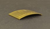
It was then a simple matter to just clamp the cover in the template and drill the four 0.45mm dia. holes, useful if you have more than one to do.

9 Cab 013B.jpg

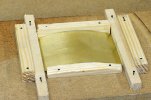
To fit the cover in the correct position in the centre of the roof I first framed round the edges of the roof with stripwood.

10 Cab 014B.jpg

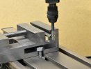
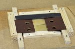
3 pieces of Bakalite were then trimmed in the milling machine to give parallel sides, the first was fitted at the rear to space the cover the correct distance from the back of the roof. The other two were trimmed together so they were exactly the same width and gradually reduced until they fitted between the sides of the frame and the sides of the cover, which then placed the cover exactly in the centre of the roof.


11 Cab 015B.jpg

The completed cab roof......


12 Cab 016B.jpg

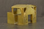
......and in place on the cab, which is now complete on the outside - just got to worry about the inside details now. With regard to the use of pins in holes for bolts and rivets, there are 109 on the finished cab unit !

tbc
 

J Whit

New Member
The cab roof requires 6 bolts for which I hadn't allowed half etched dimples, 4 of which were in a line at the rear of the opening hatch cover. Rather than trying to mark these 4 out on the cover I made a template to make the job easier and more accurate.


I have one of the early Unimats which has been mainly used with its vertical post as a drilling machine and this has a leadscrew with a fairly accurate metric thread. One turn of the handwheel gives 1mm and its marked with 0.05mm divisions. A piece of scrap brass sheet was bent into an 'L' shape and fixed in the vice and a scriber mounted in the 3 jaw chuck. The scriber was then used to make a series of pop marks in a line with the spacing required on the cover. A couple of extra pop marks were added before and after the required holes corresponding to the edge of the cover plus 0.45mm. The four middle holes were then drilled out to the size required for the pins representing the bolts. The two extra end holes were drilled out 0.9mm and short lengths of 0.9mm brass wire soldered in them, these serve to locate the cover correctly on each side in relation to the bolt holes.


Using the 0.9mm pins as a guide with a suitable spacer another small piece of brass was soldered to the template to give the correct distance for the line of holes from the end of the cover. Ignore the extra holes and score marks, I did say it was a piece of scrap brass !


View attachment 178578

It was then a simple matter to just clamp the cover in the template and drill the four 0.45mm dia. holes, useful if you have more than one to do.


View attachment 178579

To fit the cover in the correct position in the centre of the roof I first framed round the edges of the roof with stripwood.


View attachment 178580

3 pieces of Bakalite were then trimmed in the milling machine to give parallel sides, the first was fitted at the rear to space the cover the correct distance from the back of the roof. The other two were trimmed together so they were exactly the same width and gradually reduced until they fitted between the sides of the frame and the sides of the cover, which then placed the cover exactly in the centre of the roof.


View attachment 178581

The completed cab roof......


View attachment 178582

......and in place on the cab, which is now complete on the outside - just got to worry about the inside details now. With regard to the use of pins in holes for bolts and rivets, there are 109 on the finished cab unit !

tbc
As always , very impressive model making , I do hope you are able and desire to finish , will be probably the best model of an Austerity ever ! , out of interest does the 'sunshine roof ' open ?
 

David Waite

Western Thunderer
Hi PhilH
I have just read through your post on MOVING COAL your attention to detail is outstanding with all your modelling and I can see you have put a lot of thought into designing the working coal loading & unloading models, they are also a piece of beautiful engineering, I have been thinking of various ways to make contact terminals for my lift up sections and your Bayonet contacts have given me another option.
David.
 

PhilH

Western Thunderer
Thanks for your comments David and J Whit, and no the cab hatch doesn't slide open - so unfortunately its not "probably the best model of an Austerity ever" :(


Coupling Rods 001B.jpg

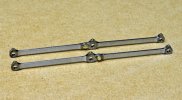
The coupling rods were laser cut from 2mm thick mild steel as previously shown in Post #53. They require a certain amount of finishing by smoothing out the laser cut surface, and I allowed an extra 0.1mm round the perimeters. However after doing the first set of 4 rods I found that 0.05mm would have been quite sufficient. The laser cutting saves the time needed to cut out and file to shape, gives a more accurate result and its easy to add spares, useful when setting up machining operations (or making mistakes !).


Coupling Rods 002B.jpg

The first machining carried out was cutting the slot for the fork in the hinged joint with a slitting saw in the lathe.


Coupling Rods 003B.jpg

Next was cutting the corresponding tongue for the joint in the milling machine. By placing the rod on the base of the vice and cutting one side, then flipping it over and giving the other side the same depth of cut the tongue will be in the centre. Just need to set the depth of cut to give the tongue the right thickness then all the rods can be done at the same time. The small piece of round brass is to mark the end of the cut. It has a small spigot on the bottom loosely fitting into the crank pin hole. As the end mill gets close I give it very light cuts until the brass just moves, indicating the cut has gone as far as required. If it flies off you know you've gone too far !


Coupling Rods 004B.jpg

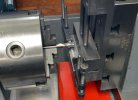
The rods were thinned on each side between the bosses with a ¼" end mill in the lathe. They were clamped to a steel plate held in the vice on the vertical slide with two spigots in the crank pin holes, so that all the rods could be fixed in exactly the same position. By noting the readings for each end of the length of required cut on the cross slide and required depth of cut on the vertical slide on the first rod, the process could be repeated on all the other rods without requiring any further measurement.

tbc
 

PhilH

Western Thunderer
Coupling Rods 005B.jpg

The completed coupling rods. The hinged joint is fixed with a 14BA bolt with the nut and washer filed down to a suitable size. The oil cups on top of the bosses are pins with the heads filed to hexagonal shape.


Coupling Rods 006B.jpg

The rods fixed to the chassis. The 12BA nuts on the crank pins are temporary - perhaps ?


19014B.jpg

On the prototype the rods are fixed on the crank pin by a round collar held in place with a taper pin. So the proposal is to make similar round collars threaded 12BA with a short length of pin sticking out to aid tightening. Well that's the idea anyway :rolleyes:
I decided to miss out on the extra small bolts top and bottom of the boss and the split pin on the hinged joint.


It runs well enough on test with no signs of binding.
tbc
 

PhilH

Western Thunderer
21 Chassis 001.jpg

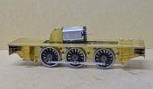
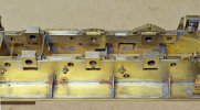
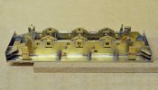
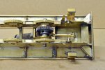
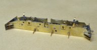
The axleboxes are sprung, but the front and rear pair sit on 12BA screws set to give the correct ride height - i.e. they can only move in a downward direction. The centre pair can move up or down. With a relatively short wheelbase I thought it would be difficult to get the loco sitting level and at the right height by relying on the springs alone.
Lots of rather untidy soldering visible !


22 Chassis 002.jpg

The axleboxes are held in place by retainers fixed with 12BA screws (centre rear) and the dummy cast brass springs are then fixed to the retainers (right rear).


23 Chassis 003.jpg


24 Wheels 001.jpg

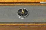
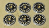
The wheels were rubbed on a flat oilstone to check whether the axle seating on the centre brass bush was level with the wheel treads. If not of course the wheel will not run true. A couple were out and required further treatment by rubbing on emery paper on flat surface then finishing on the oilstone.


25 Wheels 002.jpg

The depth of the countersink on the front of the wheels varied - slightly too deep on the outer pair and not quite deep enough on the centre pair.


26 Motor Gearbox 001.jpg

I tried various motor/gearbox types but found the Slaters GB40L to be the most suitable for the space available.


27 Motor Gearbox 002.jpg

To keep the motor in position but allow a certain amount of up and down movement I added a stay or strut (whatever you want to call it) pivotted to a gearbox spacer.


28 Motor Gearbox 003.jpg

.... and anchored to a fixed pivot under the cab floor. (it looks as though the nut on the pivot is missing but the fork is threaded both sides so the 10BA screw can be tightened without clamping the fork against the pivot)

tbc
 

michael mott

Western Thunderer
Lovely work on the axle boxes and retaining method. I also like the solution for allowing the motor to be able adjust with the axle. The taper pins for the retainer collars can be had from the watchmaker suppliers the smallest sizes work well for me.
Michael
 

spikey faz

Western Thunderer

The axleboxes are sprung, but the front and rear pair sit on 12BA screws set to give the correct ride height - i.e. they can only move in a downward direction. The centre pair can move up or down. With a relatively short wheelbase I thought it would be difficult to get the loco sitting level and at the right height by relying on the springs alone.
Lots of rather untidy soldering visible !


The axleboxes are held in place by retainers fixed with 12BA screws (centre rear) and the dummy cast brass springs are then fixed to the retainers (right rear).


The wheels were rubbed on a flat oilstone to check whether the axle seating on the centre brass bush was level with the wheel treads. If not of course the wheel will not run true. A couple were out and required further treatment by rubbing on emery paper on flat surface then finishing on the oilstone.


The depth of the countersink on the front of the wheels varied - slightly too deep on the outer pair and not quite deep enough on the centre pair.


View attachment 180246

I tried various motor/gearbox types but found the Slaters GB40L to be the most suitable for the space available.


View attachment 180247

To keep the motor in position but allow a certain amount of up and down movement I added a stay or strut (whatever you want to call it) pivotted to a gearbox spacer.


.... and anchored to a fixed pivot under the cab floor. (it looks as though the nut on the pivot is missing but the fork is threaded both sides so the 10BA screw can be tightened without clamping the fork against the pivot)

tbc
I've previously eyed up the Slaters gearbox/motor combination, but never actually ended up buying one due to not being able to find any reviews of its performance. I'd be interested to know what you think of it.

Mike
 

PhilH

Western Thunderer
I've previously eyed up the Slaters gearbox/motor combination, but never actually ended up buying one due to not being able to find any reviews of its performance. I'd be interested to know what you think of it.
Mike
Mike,
I was somewhat tied with finding a combination to fit the loco and I wanted a helical gearbox instead of worm. It does seem to be well made and the spacers are set into the gearbox sides rather than just held by the screws. I found this out when I removed one spacer to fit the bracket for the retaining stay and it took some effort to prise apart the side frames. It runs reasonably quiet as you can see in the video in Post #106, at that stage there was only a small amount of oil on the gears as supplied and there was no oil on the loco axleboxes or coupling rods. So at this stage I'm quite happy with it.
 

John Baker

Western Thunderer
I've used two Slaters gearboxes now and both have performed really very well. Excellent build quality an smooth running. Perhaps a little noisier than I'd have liked, but not so much so that I wouldn't buy again. I haven't given them loads of miles though, so I can't comment on the longevity of performance....
 

PhilH

Western Thunderer
A bit more progress:


29B WITCH.jpg

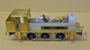
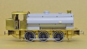
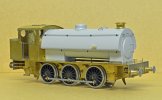
Buffers added and 3D printed tank and boiler unit fixed in position.


30 Buffers.jpg

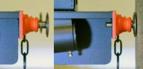
The buffers are Markits BR/WD (Ref.M7BufLBRwd16) which are near enough exactly right. They just lack the small square projections on top of the stock near the head end. These were added by pins with the heads filed square. I don't like the large nut on the end of buffers behind the buffer beam and in this case there wasn't room anyway with the triangular brackets behind the buffer beam. So the threaded ends were cut off and holes drilled for pins to retain the heads. The buffer fixing bolts are pins with the heads filed to hexagonal shape and soldered into the holes already provided. With all the soldered bits on and around the buffers I didn't fancy trying to solder the buffers to the buffer beams so they are fixed with epoxy. If they come off I'll just have to stick 'em back on again !


31 WITCH.jpg

There is plenty of room for the decoder, stay alive, speaker and a 1.5amp fuse in the tank/boiler, just temporarily placed in position for now. I'm not sure whether to permanently assemble the tank/smokebox/boiler/firebox as a unit in which case the electrical gubbins would have to be poked in position from the firebox end, or keep the parts separate. Alexander Clark, the designer of the 3D parts, made a great job of making the parts interlock together. At the cab end its all retained by the angle brackets on the cab front and at the other end the smokebox is retained by a single 8BA screw through the base. If the 4 parts are separate it just needs some means of securing the front end of the tank to the smokebox, maybe via the chimney, although I would like to keep the chimney open as far as possible to enable the sound from the speaker to come out where it should. There should be a small gap between the underside of the tank and the smokebox (approx. ½" according to the works GA drawing) as the tank sits on brackets on each side of the smokebox (not yet provided) rather than the top of the smokebox. Similarly there should be a gap between the base of the chimney and the tank, as the chimney sits on the top of the smokebox not the tank.


31A Austerity chimneys.jpg

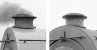
Chimneys on HE 3163 (left) and HE 3694 (right) both at Bold Colliery, but fit them with a gap like that underneath on a model and people would think you've got it wrong !


32 WITCH.jpg

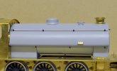
I gave the 3D printed parts up to 5 coats of primer (Tamiya) rubbed down between each coat before I was satisfied with the results. The tank had a distinct sag or bow along its bottom edge which required flattening and reshaping the wrap under curve. There are still signs of it at each end and a bit more reshaping of the curve would have been desirable. Handrails supports are by Ron Chaplin and I could do with more but they don't seem to be available now. The ones that are available all seem to have tapered stems which aren't appropriate for these locos. The brass tank steps are soldered at the back to two 0.5mm brass wires (you may just be able to see the end of these wires filed flush at the front) which pass through holes in the tank and are then bent over inside. On the prototype the steps are welded to the tank.


33B WITCH.jpg


34B WITCH.jpg

The motor/gearbox seemed reasonably quiet when the chassis was on test off the track, but now the loco is running on the track it has a distinct "whine" at moderate speeds which I don't find acceptable, so I may have to look for alternatives.
 
Last edited:

adrian

Flying Squad
The buffers are Markits BR/WD (Ref.M7BufLBRwd16) which are near enough exactly right. They just lack the small square projections on top of the stock near the head end. These were added by pins with the heads filed square. I don't like the large nut on the end of buffers behind the buffer beam and in this case there wasn't room anyway with the triangular brackets behind the buffer beam. So the threaded ends were cut off and holes drilled for pins to retain the heads. The buffer fixing bolts are pins with the heads filed to hexagonal shape and soldered into the holes already provided.
I like that - might have to steal that idea for my Sentinel build as clearances are very tight behind the buffer beam.
 

PhilH

Western Thunderer
I like that - might have to steal that idea for my Sentinel build as clearances are very tight behind the buffer beam.

Adrian,
If you're really short of space behind the buffer beam and are making your own buffer heads, one idea I've used previously on a Minerva Peckett was to drill and tap the buffer stem 10 or 12BA (depending on the diameter of the stem) and use a countersink screw to retain the head. The size of the screw head should be just a bit bigger than the stem to retain the head in position.


Minerva Peckett - new buffers.jpg
 

Jim Read

Active Member
Hello Phil,
I've been thinking about your 'whine' it could be a high frequency signal getting into it.
A 63 Volt 0.1 uF (100nF) which is a very small capacitor across the motor terminals might stop the whine by grounding the signal.
Some here on eBay
Cheers - Jim
 

simond

Western Thunderer
Hello Phil,
I've been thinking about your 'whine' it could be a high frequency signal getting into it.
A 63 Volt 0.1 uF (100nF) which is a very small capacitor across the motor terminals might stop the whine by grounding the signal.
Some here on eBay
Cheers - Jim
Shame it can’t fix the whining gearbox on Portescaps…
 
Last edited:

PhilH

Western Thunderer
I contacted YouChoos who supplied the decoder to enquire whether the provision of a capacitor across the motor terminals might affect its performance. They advised that it might affect the Back EMF features of the decoder and instead I should experiment with the motor control and Back EMF CVs, changing CV #112 to 32 and then trying different values of CV #56. After doing that I couldn't really detect any improvement so I did try adding the capacitor but there again found no noticeable difference. However the "whine" is only evident at higher speeds, and I don't think its noticeable on the following video:


There's a slight "Grrr" (that's about the best way I can describe it) at the start of any movement, but the slow speed running is excellent as demonstrated in the last clip on the video. I'm reasonably sure the "whine" when it does occur comes from the gearbox rather than the motor. Maybe that's a characteristic of helical gearboxes - smoother running than a worm but with a noticeable whine at higher speeds ????
 

PhilH

Western Thunderer
I've decided to press on with the second Austerity and get it up to the same stage as the first, then worry about all the extra details required for the two locos together. This one will be the Giesl ejector version as Hunslet 3823/54 named WARRIOR, running on the Walkden Railway between 1967 (when it received the Giesl ejector) and the line's closure in October 1970.


35 WARRIOR Chassis.jpg

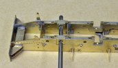
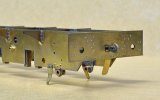
The basic chassis was completed some time ago (3½ years - Blimey !) so the first job was to set the front and rear axleboxes to the correct height on the 12BA screws as on the first loco (Post #107). All the axleboxes are numbered with pop marks so they all go back in the same positions.


36 WARRIOR Chassis.jpg

A 3/16" reamer was run through the axle holes by hand to make sure the holes lined up correctly.


37 WARRIOR Chassis.jpg

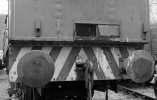
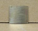
There are two differences in the rear buffer beam from the first loco. A plate hangs vertically down from the centre of the buffer beam and this was to protect the underfeed stoker pipework from damage by the coupling chain swinging forward. The coupling hook is located in a slot giving some sideways movement instead of directly into the buffer beam. This was because the hook was extended when the loco was fitted with the extended bunker and extensions to the buffers (see Post #27 for details). It was shortened back to normal length when the bunker extension was removed. I've fixed the hook in position as it didn't think it actually needed any sideways movement.


38 37712B.jpg

After preservation on the Dean Forest Railway in 1986 showing the revised coupling arrangement. The vertical plate below the buffer beam was removed at the same time as the underfeed stoker before the loco was sent from Walkden to Bickershaw Colliery. However the bunker still retains the small sliding door fitted to underfeed stoker locos, probably for access in case of a blockage in the stoker inlet at the bottom of the bunker. Note the larger than normal buffer heads. For some reason Austerities sent to Bickershaw Colliery had larger diameter buffer heads fitted to the rear of the loco.

tbc
 
Top