Nick Dunhill's Workbench - BR STD 3 from a Scorpio kit.

Nick Dunhill

Western Thunderer
I am quite excited about this build. I like Standards and haven't had the opportunity to make one recently. Only Scorpio do a kit for the model, and it has its origins with Jim Harris's Acorn, later Transport Age range. Scorpio acquired the range some time ago and did what they could to improve the product and Jeff had a built up model on his stall at Kettering and said it was buildable. So armed with an elastic budget and some determination it's on with the soldering iron.

55135684956_b31c6349e0_b.jpg

55135570898_8612068a58_b.jpg

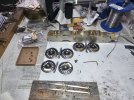
The client has supplied me with a set of detailed drawings for the loco, so the uncertainty lies with the tender. I decided to tackle that first. The first job was the inner chassis. Firstly I cut U shaped holes in the chassis side to accept Slater's square brass bearings on the front and middle tender axles. The bearing location was measured and the bearing located using 1.5 x 1.5 mm L section brass. I added height adjusters.

55136104695_42774c3bc1_b.jpg

The rear axle used the top hat bearings supplied in the kit.

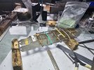
The chassis sides have a big fold that needs making along the top of the panel. I folded the first side and it came out a bit distorted, so rather than mucking around trying to straighten it I cut the top off, straightened the parts and soldered them together. I did the same with the second side, and noticed that the fold line wasn't drawn completely straight, and hence the curvature on making the initial fold. The kit is hand drawn, and the edges and fold lines are a bit wobbly. It is easily filed straight though, checking for squareness as I go.

Anyway the inner chassis came out well. I used the simplified castings for the tender brake rigging and water scoop, deciding it would be better to spend the budget on the visible parts of the model later.

55135586513_c39dc8fec6_b.jpg

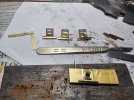
Next I made the tender front and the sections behind it. The panels for the lockers behind the front panel were not quite the correct size, so I had to make a couple of new parts. Also the curvature of the top sections of the tender front didn't match, so I decided to stop building that area until I had got a little further with the body and could find some point of reference for everything. There's no point in making a big sub assembly and having to take it apart later to make it fit. At this stage I went back to the outer frames and buffer/drag beams. The footplate was fine and the front drag beam folded down nicely. The fold line for the buffer beam was too close to half etched sections on the buffer beam front, and I would have just distorted it....badly. I cut off the buffer beam along the fold line and soldered it on instead. The outer chassis sides were about 4 mm too short, so I extended them by butt soldering a bit of scrap etch to the rear (the join is hidden by the rear steps). The locating hole for the rear axlebox is around 1.5 mm to far to the rear, so that was moved too. I fitted up the steps provided and added buffers to the drag beam and bumpers to the drag box. A fixing screw for the loco to tender coupling was improvised, and the tender floor had to modified a little so that the fixing nuts could be located sensibly.

55135989969_4f86c438a7_b.jpg

The axlebox and spring castings were replaced by some Ragstone items provided by the client. I bought some Ragstone buffers from Andy at Kettering and will convert them to be self contained next week before fitting them to the beam.

This is the state of play as I type.

55135400651_df32cfc5a6_b.jpg
 

richard carr

Western Thunderer
Nice work Nick, but wouldn't it have been cheaper to buy a MOK tender and build that than mess around with this. SOmething for next time if there is one.

Richard
 

7mmMick

Western Thunderer
Looking forward to seeing this come together Nick, some scratch building needed on the loco I bet ! I fancy one of these for myself as Hull has a few of them from new. Like Richard suggests I thought about an MOK tender and then the ex Acorn loco. I'm not sure how different the 76000 is? Maybe the 77000 is a smaller boiler and then more of the MOK 76000 kit could be used?

Mick
 

southern rambler

Active Member
Hi Nick
77014 was moved to Guildford shed at the end of steam to work some special chartered trips across the outer London suburban branch line routes due to its lighter axle loading to Chessington South, Shepperton and Windsor & Eaton Riverside.
She never went back north and ended the last day of steam either working out of Bournemouth or Weymouth so I am keeping my eye on this build as I have considered purchasing the same kit.

Kind regards,

Paul.
 

Nick Dunhill

Western Thunderer
I never thought about a MOK tender, but the 4s had a BR2 tender and the 3s a BR2A. Not sure what the difference is. Be interesting to see whether the cost of a second tender would be offset by the time saving in making it? We'll never know, but MOK kits are complex and it might end up costing more. If you're building for yourself this isn't an issue of course. The tender has been ok so far.... I'm not that sure about the differences in the loco. The basic measurements are the same except for wheels.

We will make a judgement on the quality of the kit when it is done. My expectations have been adjusted accordingly, so no damning comments yet. Most of the castings are heading into the sin-bin...........
 

mickoo

Western Thunderer
I never thought about a MOK tender, but the 4s had a BR2 tender and the 3s a BR2A. Not sure what the difference is. Be interesting to see whether the cost of a second tender would be offset by the time saving in making it? We'll never know, but MOK kits are complex and it might end up costing more. If you're building for yourself this isn't an issue of course. The tender has been ok so far.... I'm not that sure about the differences in the loco. The basic measurements are the same except for wheels.

We will make a judgement on the quality of the kit when it is done. My expectations have been adjusted accordingly, so no damning comments yet. Most of the castings are heading into the sin-bin...........
The MOK kits does the 2 and 2A, the main difference is that the 2A has a fall plate and gangway doors, the 2 is fitted to engines with the cab floor extended and doors added to the engine, thus no fall plate or tender doors. The MOK kit doesn't cover the 2/2A tenders with the small spectacle windows though, something Dave is/will be looking into I believe.
 

Nick Dunhill

Western Thunderer
The build has progressed. I had my doubts about the tender body etches, but I was wrong to and it was mainly good news. The dimples in the rear of the etch panels, etched as guides for my rivet punch were way way too big (as were all of the pre etched holes) so careful use of the guide on my forming tool was needed. I cut the half etched bunker sides off the main etches because I was convinced that I wouldn't be able to make the fold tightly enough. Then I went for it with bars that were the just under the correct radius and, using the bunker rear as a guide, managed to form the desired shapes into the tender body sides.

55142168381_97a853090f_b.jpg

It was a big relief as failure would have triggered a lot of scratchbuilding and budget induced stress.

Next I fitted up the coal space rear. The portion of that panel that sits inside the body needed a bit of reducing here and there to stop it bulging out the body sides. The coal space sides needed a little reduction in length but were refitted. If you cut them off as I did they only just fit, as you have removed some material with the saw blade. It's important to carefully cut them off right along the tender body top, where they become half etched.

The rear of the tender front and 'roof' needed some substantial mods to make it fit. The coal space top sides at the front don't meet the top of the tender front panel so need extending. I extended it with a bit of boiler band and made good with solder. the 'roof' is too short, but can be filled with solder and you have to make the strange upstand on the rear of the tender front assembly. The fire iron tunnel also needs some work to make it fit.

55141275397_13bd115b9e_b.jpg

I also made the slacking pipe tube fitted to the front wall. My plan is to glue a plastic card 'shelf' inside the top of the coal space and glue a coal load on top of it. In this way I won't have to fit the coal space interior and waste time/budget making it fit (or not).

The buffer castings in the kit are blind(!!), so I bought replacements from Andy at Ragstone and made them self contained. I later found out that MOK buffers are designed to be self contained!

55142168396_864d6f129a_b.jpg

Attention turned to the rear platform. I had to make the steps that sit on the rear of the sloping sides of the body. The kit has some castings that were ok but for a different tender, so didn't fit this one (or the patterns were made without taking any measurements). I added all the handrails a scoop dome and filler.

55142172001_3160962347_b.jpg

The lamp iron etches were wrong, but I managed to re jig them to fit, and the distinctive pair of lifting eyes were a bit wrong, so I made new ones.

Overall the tender etches have made a pretty good BR 2A tender so far, but there is a bit of remedial fiddling to be done here and there. Perhaps I've been a bit unfair on old Jim H in the past. Or maybe the Ennis folks made a decent job of rejigging it all. We will see as the build progresses.
 

Nick Dunhill

Western Thunderer
Well, I made a tender from an Acorn/Transport Age/Scorpio/Jim Harris kit with no increase in blood pressure.

55145592253_d19bee542d_b.jpg

55145435446_0a9132f093_b.jpg

55145435446_0a9132f093_b.jpg

There was a fair amount of scratchbuilding to be done, but only really on the small components. I had to cut a new footplate at the front, and the slopey thing that is at the bottom of the cab front. All the castings have been replaced by better ones from Ragstone and handmade ones like this:

55135779750_91090d4170_b.jpg

The ladder at the back of the tender turned into a bit of a nightmare, but entirely of my own making. I was removing the etching cusps from the hockey stick shaped bits and one got caught in my sanding disc. It was badly bent and broke in half. It was fixed thus:

55145668654_0f67be4741_b.jpg

The pre etched holes in the ladder sides are 1.1 mm and really the treads are 0.9 mm. I slipped some thin-walled tube (1.1 mm OD, 0.9 mm ID) over the ends of the treads to take up the difference. There were no fixing brackets for the ladder in the kit.

Loco next week..........
 

Nick Dunhill

Western Thunderer
I had to take a little break from this build in the middle part of this week as I had a loco back from paint.

55158369271_06f87669e2_b.jpg

55158528563_ab40e8e21b_b.jpg

I did manage to make a start on the loco though. I started by making up the coupling rods from the etches on the kit. I did use a few crankpin boss overlays out of my bits box, but ended up with some nice rods.

55158528533_c6793f4f70_b.jpg

55158751200_f8ba193736_b.jpg

I moved on to the chassis frames and planted some pieces on the bottom of them to make them look more like the real things.

55157469367_03f883f4c4_b.jpg

There were a selection of frame stays in the kit. Some on the original etches and some added later by Scorpio in an attempt to upgrade/correct the kit. I decided to make my own custom axleboxes. I normally make them straddle the frames (the frames run in the slot in the axlebox) but the drawing shows the loco had axleboxes mounted inside the frames. The horn guides were built round Slater's standard square hornblocks/axleboxes, and the top and bottom is made from L section brass and the sides from T section. The T section was modified to fit the axleboxes, and the top L section had a hole drilled and tapped 12 BA for a height adjusting screw. I built a simple jig in which to assemble the items.

55158369441_1c87b7930e_b.jpg

The basic chassis was assembled on a piece of graph paper on a plate glass sheet, and the axleboxes located using the rods.

55158528683_67f7b768fb_b.jpg

55158528703_06f301d839_b.jpg

I began to prepare the Slater's wheelsets but ran out of time. I'll begin with that next week.

55158751360_920426dc5d_b.jpg
 

Attachments

  • 55158751360_920426dc5d_b.jpg
    55158751360_920426dc5d_b.jpg
    297.5 KB · Views: 16
  • 55158528683_67f7b768fb_b.jpg
    55158528683_67f7b768fb_b.jpg
    287.9 KB · Views: 12
  • 55158369441_1c87b7930e_b.jpg
    55158369441_1c87b7930e_b.jpg
    278.6 KB · Views: 12
Last edited:

Nick Dunhill

Western Thunderer
I have chugged on a bit further with the chassis this week. Progress varies from quickish to glacial as many parts have to be 'processed' to fit.

First up I fitted up the wheels and levelled the chassis. All went well so I installed the motor/gearbox and got a nice free running mechanism.

55171624616_6826b0d99d_b.jpg

I decided I would make the cylinder block first. I assumed (assumption being the mother of all f*** ups) that the etchings for the cylinder front and back could be placed into the slots in the chassis and their correct position for the wrappers would be obtained. I ended up making some spacers for the cylinder front/back etches to get them the correct distance apart for the cylinder wrappers. The slots in the chassis needed to be widened slightly to allow the basic cylinder block to fit (I would revisit them later). I added the washout plugs and the boxy thing that sits on the cylinder tops. I had to make the latter, as the whitemetal casting supplied for this was really a fishing weight.

The kit has an alternative pair of cylinder front and rear etches that the instructions advise not to use. I cut them up and planted them on the front and rear of the cylinders assembly to improve their appearance. I pondered the idea of buying some MOK Std 4 castings for the cylinder fittings, but decided against as they might not fit anyway. I tried to fit up the white metal castings for the cylinder heads (needed a big mod) and the valve cap and guide. The valve cap casting was fine but the valve guide casting in the kit was also a fishing weight, this time a brass one!

I decided to take a break from the stress-inducing cylinder block and make the brakes. The brake hangers and blocks are castings in whitemetal. If you don't mind whitemetal (and my budget didn't mind whitemetal) they are actually good castings and fit well. The brake spreaders needed to be replaced as they had shackles for a different brake rigging set up. I made the rest of the brake system from scratch.

55172014320_eb3c2cd74e_b.jpg

I then went back to the cylinders and sorted out the slidebar and crosshead castings. They were also quite ok after some fettling. I fitted them up to the rear of the cylinder block and made the con rods from the etchings in the kit.

55171624746_8e1c660920_b.jpg

The last job of the week was to fit everything up and see if the crossheads and crankpins came into conflict. They did not, and I took it as a win until I spotted the position of the cylinders.

55172014415_7305903f0b_b.jpg

I noticed that the cylinders sat fat too low in the slots. This was like getting an awkward email at 4.30 on a friday according to my wife. (I have been lucky and never had to work in an office.) I measured up and made a paper positioning template, and finally got the cylinders into the correct location. I took measurements from the GA and located the piston rod gland at the right height above the rail head, and used my paper template to get the correct slope.

55171624736_18fe16bca3_b.jpg

55171624796_4533e16748_b.jpg

I'm trying not to take too many measurements from the GA in case I open a large can o'worms, but so far so good. The cylinder block is in the correct position with respect to the middle driver centre. Jim H could use a ruler occasionally when it suited him. Perhaps next week I should make the cab and footplate to see if that fits. I'm going to have a stress relieving YouTube yoga video ready to go first.
 

paulc

Western Thunderer
Any advice on how to make the disc stay on the pad , mine keep flying off .
Please don't say Araldite.
I will admit that I'm chopping my discs out of a 150mm sticky back sanding disc but that stays on an air sander so surely it should stick to a 25mm pad .
 

Nick Dunhill

Western Thunderer
Short pre-easter week and all that. I started making the motion bracket. The casting in the kit for the motion bracket can be seen in the last pic of my previous post, above the rule and to the left of the wheel. After several days of hacking it now looks like this.

55185141848_7700e64b0b_b.jpg

I also had to (decided to) modify the expansion links so that the radius rods move through them as the real thing. They will end up being captive, which will (not) please the painter bloke, but hey-ho so will all the (working) linkage to the mechanical lubricators.

55185241874_59e072520e_b.jpg

55185241964_8f63faff32_b.jpg

55184093672_419717038f_b.jpg

The mechanical lube castings are from Ragstone, as are the much modified linkage rods. I hope they fit under the footplate. I should have made that first, as it might end up being a bit of a wasted mission. The lubes are at the correct height above the rail, according to the GA, but.....

I went to a birthday meal on wednesday evening and might have had too much Cremant! Luckily I saved something 'easy' for the last working day of the week. I made the pony truck, and then upgraded it a bit.

55184093632_7af8d6ce20_b.jpg

Motion next week, or maybe the footplate.....or sanders......or pick-ups. Or all of the above.
 

Nick Dunhill

Western Thunderer
Well I did leave the footplate until later which may come back to bite me in the bum, but I did finish (more or less) the motion, sanders and pick ups.

The first job of the week was to attach the motion brackets. I took a measurement of the distance the motion bracket should lie from the centre of the cylinders, and it matched the length of the slide bars and the distance to the centre of the centre driver....more or less.

55200099181_3ff1e34bff_b.jpg

I made the combination lever from the kit etches. The union link was also from the kit etches but modified slightly to look correct and to link up with the crosshead. I had to make some mods to the valve rod as the casting is not from the same source as the valve guide. I acquired some nice castings for the radius rod lifting links, weigh shaft and reversing mechanism. Gleefully accepted and attached.

55200099196_57ac18aa1b_b.jpg

I had to measure and drill a hole in the frames for the weighshaft, as there was no pre etched one.

The return crank was partly scratchbuilt and the eccentric rod came from the same source as the weighshaft castings. I had to make a brass cover for the eccentric rod, but overall the cast rod was much better than the etchings supplied in the kit.

55200346909_6183175244_b.jpg

55199204527_dc15b4e955_b.jpg

The hockey stick thingies are the sanding pipe brackets. I made them as there's nothing in the kit for the sanders except for these curious random castings.

55200502300_7ae7390502_b.jpg

I couldn't work out how the sand boxes were arranged from the GA, but Mick Davies sent me a pic of an MOK Std 4 chassis he's made and all became apparent. It all had to be scratchbuild of course.

55200501610_ae9fffa6af_b.jpg

55200099391_3f2e3c5ef3_b.jpg

The PCB is in place for the pick ups but I ran out of time to make the wires.

This is the state of play so far on the chassis. It is a bit of a mongrel and has required a lot of work rounds, but I have got a nice representation of the Std 3 chassis. Body next week, let's hope.......

55199204667_4524f3dfb2_b.jpg
 
Last edited:

Nick Dunhill

Western Thunderer
Here is all the above assembled.

55213538297_19fb4de59c_b.jpg

I had to make a few motion pins and fasten the return crank to the middle driving wheel crankpin (a 12BA brass screw). My method of attaching the return crank is to drill and tap the return crank 12 BA. then screw the return crank onto the crankpin. The correct position of the return crank can be achieved by turning the screw in the wheel. When the return crank is tight and in the correct position the excess screw can be cut off and the return crank overlay added.

The chassis runs very freely without any binding, as it should.

I couldn't put off building the footplate and cab any longer, so I began with the footplate. I braced the fooplate with some T section brass strips made from scrap. Past (bitter) experience has taught me that folding down a thin valence on the edge of the footplate is a non-runner. In the past I have ended up with a distorted banana-shaped footplate and valence, so I cut off the valence and soldered it back on. I had to cut off the front, dropping, sections of the valence as they were different lengths and didn't match the footplate. There's a convenient panel joint to cut the valence at the front.

55214683079_17984a300b_b.jpg

I had to make a new buffer beam as the holes for the buffers were in the wrong place.

I offered the footplate up to the chassis and it wouldn't land properly. After a lot of measuring I realised that the upper and lower platforms were around 1.7 mm too close. The sloping bit was around 2.3 mm too short according to Mr Pythagoras.

55214837650_432df56611_b.jpg

I made a new sloping section and the valences needed to be replaced too.

55214683109_35470a7bcb_b.jpg

I completed the front of the footplate with steps etc.

55214702464_d43be4d3ef_b.jpg

You can see that I marked out but didn't fully form the cut out for the bottom of the smokebox just in case it needs to be altered (place your bets).

With that finished I moved on to the cab. I used the GA to get the correct angles in the cab front and offered it up to the rear of the footplate. Jim H had designed the cab front etch with the wrong angles, and the whole thing was about 2.2 mm too wide. Although on further inspection It turned out that the footplate was wider at the front than the rear. This was curious as I had added the T section braces before cutting the etch out of the sheet. With the footplate adjusted I cut a slice of the required thickness out of the centre of the cab front.

55214683179_5697ab5551_b.jpg

The cab sides were hellishly difficult to locate in the correct position on the cab front. I made a few fixtures to help get them soldered on in the correct position and at right angles.

55214837765_70927d9b12_b.jpg

55214683204_fe041d0fd9_b.jpg

The fixtures on the inside of the cab locate the side at a right angle to the front and get the bottom of the cab vertical. The wrap round fixture in the top pic is to line up the windows so they are at a right angle to the cab front.

55214438006_b757139441_b.jpg

I ended up with a cab that was how it should be, but will need to fill in the footplate top to correct the wrong angles of the cab front.

There wasn't really anything left in the etches that was usable for the cab. I made around 30 panels to complete the cab footplate, drag beam and floor, and to close up the cab front.

55214594173_a27c4f9f1e_b.jpg

55214683424_3871a35f4b_b.jpg

I finished the week by adding the cab window surrounds and inner frames. I also made a start adding some of the structures and details on the cab interior.

55213538567_96661d585a_b.jpg

55214438166_75560c3980_b.jpg

Next week I will continue detailing up the cab interior and fabricating a cab roof.
 
Top