Rivermead Central

40057

Western Thunderer
The photo is not great, I’m afraid, as the daylight was fading fast. Good enough though to show the storage shed now has a door:

EDD4BADE-5506-4591-A978-B6B2E2B1DA59.jpeg

It’s the same colour scheme as I used for the yard office. I have also put some light weathering on the plinth brick work to make it less bright. A very traditional model railway building door handle: a small round-headed nail not driven all the way in.

Martin
 

40057

Western Thunderer
Goodness, the days are short now. But got outside in the daylight today to saw the ends off fourteen Bassett-Lowke sleepers. These are to make a further length of fence to go south of the storage shed, as shown here:

6A8FDDB0-97EE-4EF3-91A2-CBFFC547FB4A.jpeg

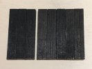
I have started to assemble the fence using the shortened sleepers:

491207AC-917F-4DE9-A60E-427ECAB88369.jpeg

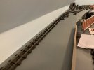
This section of fence will be just under six inches long. The adjacent ‘brick’ wall, which is mostly complete but still without its coping, and to which the storage shed will be attached, is a bit longer. So the current structure I’m making (wall, shed, fence, shelter for fire buckets) will cover a bit more than a foot of the wall of the room. Really, this seems a lot of work, too much effort, to extend the ‘wall covering’ behind the west side of the layout such a short distance. However, I decided I needed to add interest behind the tracks here because south of this point there is no room:

041375B5-532B-4035-9430-2B8E9B63EA34.jpeg

The space behind the rearmost track will allow me to insert a boundary wall/fence but really nothing else. Hence, using the wider area by the point-work leading into the north yard to add ‘scenery’:

03ADA3CF-2C5C-4216-A667-F5354FD7E9AF.jpeg

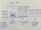
I’ve sketched in the yard signal box and the current elements under-construction. The layout is going to have an awful lot of walls — behind the tracks, separating the high and low level sections, at the front as a safety measure to guard against plunges to the floor (clockwork engines don’t necessarily stop when derailed). So to get the overall look of the layout right, I will need to use most/all the spaces available for buildings.

On a different subject, but to record the event in this thread, I am advised by Tom Mallard that Caledonian Railway no.828 is finished. It can be seen in Tom’s workbench thread.

Martin
 

John R Smith

Western Thunderer
as a safety measure to guard against plunges to the floor (clockwork engines don’t necessarily stop when derailed).

Most times that I have had a derailment the engine has stopped because the auto-stop has tripped, but I agree that caution is advised. I do envy you your space, Martin. Looking along the length of the layout in your photos makes me realise just how cramped mine is!

John
 

40057

Western Thunderer
Most times that I have had a derailment the engine has stopped because the auto-stop has tripped, but I agree that caution is advised. I do envy you your space, Martin. Looking along the length of the layout in your photos makes me realise just how cramped mine is!

John
Is there no way you can extend? Even if you have to use temporary lift out sections to join permanent installations? Or a trestle table that can be put away after use so there is a circuit trains can run around? Clockwork trains really need an end-to-end close to the distance run on one winding, or a circuit. Otherwise there just isn’t time to step back and watch them between setting them off and intervening to stop them.

What about starting a new thread on WT — the Kingswell Street railway extension? Then you’ve got to do it!

Martin
 

40057

Western Thunderer
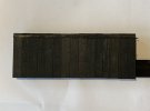
Progress with the construction of the sleeper-built fence, as described in my post #603 above:

B0F703BA-CCCE-48D5-A7BE-D5AD11571057.jpeg

The shortened sleepers are now all fastened together and glued and screwed to a length of strip wood — visible projecting from behind the fence on the right-hand side in the above photo. This length of strip wood will then be similarly fastened behind the adjacent section of ‘brick’ wall, so keeping straight the whole structure shown in the sketch in post #603. There will be two horizontal rails on the fence as per the longer length of similar fence made previously. The top rail is glued in place in the above photo, but I will fasten it with pins as well using the pilot holes drilled in the rail.

Both the ‘brick’ wall and the storage shed are well on towards completion, so I will be joining the different elements together soonish. What I have not done is started on the shelter for the fire buckets. I have in mind what I want to build, and I’m convinced I have seen similar structures, or at least photographs. But I can’t now find a picture of a real-life example. I would like to find a couple of period photos to confirm what I plan to make really did exist.

Martin
 

John R Smith

Western Thunderer
What I have not done is started on the shelter for the fire buckets. I have in mind what I want to build, and I’m convinced I have seen similar structures, or at least photographs. But I can’t now find a picture of a real-life example.
I can't recall fire buckets that I have known ever having some sort of shelter or roof above them (at least, not here in Devon and Cornwall). Now I've stuck my kneck out and said that, we will be deluged with examples from all over, of course. I don't quite see why you would want to shelter the buckets - they were just full of water, so having the rain top them up would surely be desirable?

John
 

40057

Western Thunderer
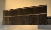
Barring a bit of paint, my short length of sleeper-built fence is finished:

0D2D98D7-74E8-4C30-B2F2-371035BA095E.jpeg

Both horizontal wooden rails are glued and nailed in place but still need a bit of black paint to cover the nail heads. The two projecting pegs at the right-hand end of the fence slot into corresponding holes in the adjoining section of ‘brick’ wall. When complete, the whole structure should be strong and rigid.

Last night, I made a further (and final) search for period photographs showing fire buckets in a shelter. I could find open-fronted cupboards containing fire-fighting equipment, including buckets, and modern free-standing racks for fire buckets which have a small roof but no walls. Also buckets in the open with lids and racks of buckets positioned under the cover of canopies or stairs. Nothing however closely resembling what I intended to build. So I have abandoned the idea of a shelter for fire buckets against the wall along from the storage shed. The real purpose of the shelter — fastened to the length of ‘brick’ wall and the baseboard — was to resist any tendency of the wall to warp and to effectively widen the base of the wall and help keep it exactly perpendicular to the ‘ground’. Any other structure in the angle between the wall and the ground in front would fulfil those functions equally well. If I can think of something suitable. Otherwise, it will just be the storage shed holding the wall and fence in position and upright.

Martin
 

John R Smith

Western Thunderer
This is the sort of fire bucket installation I am used to, here at my home station of Kingsbridge in South Devon -

Kingsbridge Station ca 1960.png

The buckets are just behind the two vans in the bay, and rather small in this photo. But they have no shelter or cover, and for me that was the norm. The date is the late 1950s, and in 1960 we went diesel with railcars instead of steam. I missed the little 45xx tanks. Only three years later, in September 1963, the last train ran and Dad and I were on it. The quiet little market town spread out below the station went back to sleep, and the railway age was over in the South Hams. Just up the hill, turn right and then left, I am at my desk in the Grammar School.

John
 
Last edited:

40057

Western Thunderer
Hi John

Nice photo!

I still have the three Bassett-Lowke fire-buckets, of course. I most likely will end up using them on one of the stations.

I take it that is a carriage shed behind the train? I would think not usual for a small branch terminus. I still like the idea of using the back track south of Cairnie Junction station as a carriage siding. If I did that, I could cover part of the siding with a carriage shed. That would address the lack of buildings in that part of the layout. As things stand, for several feet south of the point work half way down the west side of the room, the layout will consist of, back to front: boundary wall against the wall of the room, three tracks on the high level, retaining wall between the high and low levels, three tracks at the low level (Cavendish Goods), safety wall at the front of the layout. OK , a few signals, but really no scenery except walls. I am looking for ways to provide some more visual interest in this area. Against the carriage siding idea is the overall relative shortage of ‘parking’ for goods wagons. Still considering the options!

Martin
 

John R Smith

Western Thunderer
I take it that is a carriage shed behind the train? I would think not usual for a small branch terminus.

Yes, Martin, it is indeed a carriage shed, and as you say a bit posh for a little branch line. The basic construction was corrugated iron on a steel frame. I don't recall seeing them much in a mainline context, though.

John
 

40057

Western Thunderer
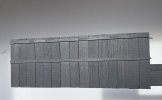
The length of sleeper-built fence is painted and finished:

8838EBDD-74FB-4165-B9CB-422C2978D27A.jpeg

The horizontal rails were brush-painted black. But then today, it has been warm enough to go outside and use a spray can to put on a light sprinkling of matt black. Not a complete coating and not enough to make the sleepers all look the same. The spray paint does however give a more uniform finish. Like The Dude’s rug, it ties the whole thing together.

Looks right to me, so no further work to be done on the fence component.

Martin
 

40057

Western Thunderer
The length of brick wall that is to go next to the length of sleeper built fence (see above), and to which the storage shed will be attached, has proved unexpectedly problematic. I was, I thought, close to completing painting the bricks when parts of the wall developed a distinctly glossy surface. I really don’t know why, but all attempts to suppress the glossiness with localised repainting failed. So, on Saturday, I decided to attack the surface with coarse sand paper and completely repaint. I now have a wall with a good matt finish. In patches, some of the previously applied paint shows through. The result, albeit achieved accidentally, I think looks pretty convincingly like old brickwork:

6020C77C-4965-4038-B6FB-2BC1BADD763A.jpeg

The other reason for slow progress is spending some time on reorganisation of storage. Given that the main base-board structure was built twenty years ago, and initially very little track put down, the vacant base-board surface inevitably got used for storage and as a work surface. So, at present, I can’t lay any more track heading south from Cairnie Junction because … the base-board is covered in track. Piles of cleaned and repaired track panels. So I have to find somewhere else to store the track panels so I can take some of them out of storage and lay them on the layout. It doesn’t feel much like ‘layout progress’ clearing and filling shelves, but it has to be done.

Martin
 

40057

Western Thunderer
Back in my post #556, I mentioned I had ordered an Intentio kit for an LMS lamp hut. I then changed my mind and decided to scratch-build a tool shed for the location, as seen most recently in post #602. However, having abandoned the idea of a ‘fire bucket shelter’, a further rethink has taken place. I’m planning to move the tool shed to roughly the centre of the brick wall it is built against, instead of having it at the northern end. The tool shed will function as a buttress for the wall, as the fire bucket shelter would also have done. With only one buttress, I need to have it in a more central position. So, provisionally, I’m minded to put the LMS lamp hut between the tool shed and the signal box. Anyway, I’m building the lamp hut kit. If I decide it’s not right for this location, I’ll use it elsewhere.

I’m impressed with the lamp hut kit. Compared with scratch building, so much quicker. I don’t expect to be able to use kits for most of the buildings required for Rivermead Central, but if a suitable kit is available I can certainly see the advantages.

With the lamp hut kit, I am departing from the designer’s intended construction in only one respect. The hut has one window and a rectangular piece of clear plastic is supplied as glazing. The plastic is the correct size to fit behind the window frame in a rectangular cut-out in the MDF that forms the side of the building. I prefer to use real glass for windows but could not cut a piece to the exact size required. So I reduced the thickness of the the MDF ‘wall’ with a file and glued a larger piece of glass behind the thinned wall:

6E5AAB88-7CCA-4C0D-B6CA-500C896D83E9.jpeg

I had to glue thin strips of MDF on the back of the glazing bars to increase their depth, otherwise they would not have been in contact with the glass.

I do think real glass generally looks much better in windows.

The lamp hut is now ready to be covered with corrugated iron sheeting:

D7F22EFD-04FC-4067-8DB7-B5844359BB48.jpeg

Martin
 

40057

Western Thunderer
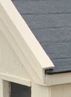
A rather un-productive week, modelling-wise. However, I have added the wooden cover over the end of the slates on one side of the storage shed’s roof:

86EF54C7-180B-4C96-B8CA-72A15C529132.jpeg

This kind of edging to the roof seems to have been common on wooden railway buildings (for example, here: Harrow No2 signal box). To make the roof edging for my storage shed, I have used L-section walnut strip-wood bought from Cornwall Model Boats. Some careful filing was required to get the end angles and length of the edging exactly right:

66781F78-3082-46AE-9D4A-92C250053B65.jpeg

Now I have to make another — opposite-handed but otherwise identical — edging piece.

I will need to add a representation of flashing where the top of the roof rests against the brick wall. I presume the flashing would also have covered the top of the wooden edging strip overlying the slates?

The storage shed is built almost entirely of wood. Certainly, all the parts that would have been wood in a similar real building are also wood in the model. Whilst clearly I can’t build models out of real bricks or stone, I do prefer to use authentic materials when that is possible. The storage shed is going to have a window made of real glass too.

Martin
 

John R Smith

Western Thunderer
I will need to add a representation of flashing where the top of the roof rests against the brick wall. I presume the flashing would also have covered the top of the wooden edging strip overlying the slates?
Martin

The wooden edging strip is really an extension of the barge board, and in the Harrow example is very similar to yours. At Harrow the barge board still tucks in underneath the slate ends, and therefore weathers them, with the added benefit that rain cannot blow in under the eaves between the board and the slates. You do not have ridge tiles and finials, so in your situation, the flashing would be chased in between the brick courses at the top, but I am not sure how the junction of the flashing and wood should be treated, as you would not ideally want water blowing underneath the wood edging and down behind the barge boards. I have no local examples of this type of roof edging to consult, sadly!

John
 

40057

Western Thunderer
Martin

The wooden edging strip is really an extension of the barge board, and in the Harrow example is very similar to yours. At Harrow the barge board still tucks in underneath the slate ends, and therefore weathers them, with the added benefit that rain cannot blow in under the eaves between the board and the slates. You do not have ridge tiles and finials, so in your situation, the flashing would be chased in between the brick courses at the top, but I am not sure how the junction of the flashing and wood should be treated, as you would not ideally want water blowing underneath the wood edging and down behind the barge boards. I have no local examples of this type of roof edging to consult, sadly!

John
Hi John

I don’t have a real example to look at either. I’m inclined to a small piece of flashing covering the top of the wooden edging and extending down onto the slates on the ‘inside’ of the edging strip. Then a length of flashing right across the top of the slates and overlapping the short lengths covering the wooden edging.

Martin
 

John R Smith

Western Thunderer
Yes, that sounds OK. Remember, with all your roofing, always start at the bottom and finish at the top. Then all your laps will be the right way round and rain cannot penetrate the Joints.
 

40057

Western Thunderer
We have a new ornament:

703AEF48-8D62-4EC8-BB22-CEE214971EB2.jpeg

I’ll get some pictures of Caledonian Railway 828 on the layout in due course. In the meantime, it’s looking very pretty and being much admired sat on the dresser.

I have wanted a model of a CR 0-6-0, and 828 in particular, for many years. The real loco is great favourite, for both my wife and me.

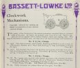
My 828 is an absolutely wonderful model and Tom Mallard’s workmanship is outstanding. What is probably not so obvious to most on WT is that an 0 gauge clockwork 828 should not really be possible at all. Essentially because it’s tiny and clockwork motors are bulky things. The short (length and height) firebox is nowhere near large enough to accommodate a motor of adequate power. So the motor is going to project either into the cab and/or forward of the firebox blocking the space under the boiler. Which would be fine if there was a nice, big cab to hide the motor. But, with a Caledonian Railway 0-6-0, the cab is tiny too. Very open and very short. It would, for example, be much easier to find space for and hide a clockwork motor in an NBR C class (=J36) 0-6-0. A similarly small locomotive, but with an 8” longer overhang behind the rear axle and an enclosed cab with only small windows. I do have an NBR 0-6-0 built nearly twenty years ago by a friend. I can state from experience that fitting in and hiding a clockwork motor is much easier in an NBR 0-6-0 than in a CR one. The length of the overhang behind the rear axle is a particularly crucial dimension. These were the motors being offered in the 1924 Bassett-Lowke catalogue (all made by Bing):

4B7F36C9-C67B-44F4-9AF1-9D026CC404E1.jpeg

The various dimensions listed would enable the scratch-builder to identify if the motor was suitable for the intended model. The ‘overhang at the driving end’ is given because it is particularly critical to determining whether the motor will fit. There will always be some overhang beyond the driven axle with a clockwork motor. Generally, in a 4-coupled motor, the overhang accommodates some of the reversing mechanism, the governor and the brake. The two 0 gauge motors offered in the 1924 catalogue have overhangs of 36.5 mm and 38 mm respectively. So, as sold, neither motor would fit in an NBR or CR 0-6-0 with the driven axle at the back. OK, then, drive the middle axle with the main spring behind. The overhanging front of the motor will, unfortunately, be painfully obvious in what should be ‘daylight’ under the front part of the boiler. The bigger problem is, due to the lack of headroom for the spring in a small boiler, if the motor has to be tilted to reduce its height, the rear wheels would then have to be on stub axles. Very unsatisfactory. OK for the middle wheels, though. So the driven axle has to be the rear axle. Which means the overhang has to be shortened — by at least c. 9 mm for an NBR 0-6-0 and c. 15 mm for a CR 0-6-0.

Which is why for many years I thought a really good model of a CR 0-6-0 was impossible in 0 gauge clockwork.

However, I took a small Bing motor to a clever clockmaker who replaced and relocated the governor and brake so the overhang could be greatly shortened. Tom Mallard agreed to take on building the model. Tom used CAD to identify the optimum position for the motor and then further reduced its size with additional modifications. The result you see in the picture above. Tom has created a brilliant and accurate model. The motor is not visible at all in the photo or from most viewing angles. There is daylight under the front part of the boiler. Hiding the motor that well would be a pretty good achievement for almost any 0 gauge clockwork locomotive. To hide a good sized clockwork motor in a CR 0-6-0 is truly astonishing.

Martin
 
Top