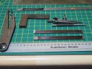
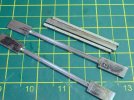
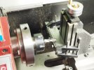
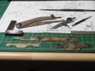
Usual problem of work pressures at the moment but I have spent a little time progressing the build. The frame drawings were finished by sketching them out over the GA drawing so I could then draw them out on the nickel-silver sheet. Nothing more complicated than a scriber, steel rule, odd-legs, dividers, square and a centre punch.
Now I could be rather smug and claim that it's a prototypical build because the looking at the GA drawing the frames appear to be built up from three distinct pieces. There is a central section with the main driving wheel hornblocks, then the front frames over the bogie are rivetted inside (so slightly narrower) the main frame. Likewise with an extra spacer the rear frame under the coal bunker is a another section. So I have drawn up the frames in 3 pieces.
However the reality is that it's a very long frame and I simply didn't have a sheet of nickel-silver of sufficient size to cut it out in one piece. I did have a couple of shorter 22' n/s sheets so cutting out the 3 sections was the expedient solution. The two sheets were soldered together, one edge was then filed straight and level to use as a reference line for marking out. These were then cut out with the piercing saw and then filed to the marked lines. Nothing at all complicated.
In discussion with modellers about scratch building and cutting out to shape one thing that crops up is the ability to file a sheet of metal to the marked line. Once again it really isn't a special skill - it's simply practice with the tools you have. I really do think anyone can achieve this if they give it a go.
It's difficult to explain in words, sometimes the exhibition workbenches are the place to learn from those with the skill. I spent hours as a teenager pestering Tony Reynalds at a Bristol exhibition one year on his methods. Absolutely brilliant engineer and spent all the time in the world taking me through what he was doing. So in a similar vein a small dive into workshop techniques, last year I bought a macro lens hence I have managed to get a couple of photos to illustrate the point.
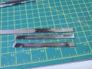
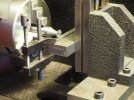
This is simply nothing more mundane than filing a sheet of metal to a marked line. Just a straight line marked on a bit of metal, if I remember correctly the bit in the photo is the front frame section by the bogie. Pick the biggest file possible, a second cut or smooth 6" at least in 7mm scale. The larger the file the easier it is control and keep straight and level - this is not a job for needle files! Personally I have my workbench at a fairly high level so for jobs like this I can be standing up in a comfortable position when filing to shape.
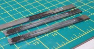
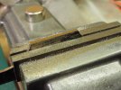
As I file down the sheet to the marked line I frequently take the material out to see which side needs a little more effort and how close to the marked line I am. The trick to note and the purpose of the following photos is to illustrate what happens when you get to the line so if you try something similar you can recognise it. When you mark out the shape for the component (the frame in this case) you place a small score in the metal, as you file down to that line if you are observant you can see a small sliver of metal peel off. In the photo below you can just see on the right hand side of the flat I'm filing a faint "thread" of metal as it seperates from the main sheet. This is a clear indication that I have reached the line on that side of the component.
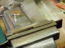
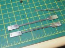
So now I know I have reached the mark on the right hand side so more filing has concentrated over to the lefthand side. As shown in the photo below this "thread" of metal has now separated along the length. This shows that I have reached the marked line along the length.
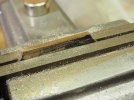
When I get to the end and the final bit separates and I end up with a curl of metal from the metal sheet. This is a good indication that I've filed to the marked line and a quick draw filing along the sheets gives a final polish and removes most to the file marks.
p.s. this is another good reason for using nickel silver sheet for scratch-building. This "line peel" is a lot harder to recognise with brass sheet.
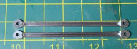
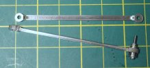
Now I'm drawing up frame spacers which is entertaining and plotting a "novel" arrangement for the rear radial truck - I'll have to see how that works out!
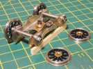
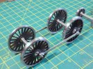
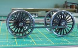
To follow up with a quick response to previous questions - another couple of photos to illustrate the front bogie arrangement to show the miniature ball races.
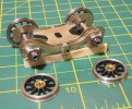
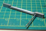
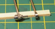
In addition to the dummy springs on the compensation beam the arrangement on this loco has a series of "cross-members" between the horn-guides. So on the the bogie below there is a securing bolt across the bottom of the horn-guide to retain the horn-block, which is the 14BA bolt in the photo - I still have to make a tube and cross-member to thread through this bolt and it acts as a tie-bar to the horn-guide on the other side. The main frames are also scant on frame spacers and also have a similar tie-bar arrangement between the horn-guides!
