7mm Steves work bench, project C1 The Ace Ivatt atlantic

topshed34a

Western Thunderer
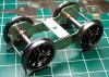
I am currently building the ACE C1 kit, not an easy task seeing as the instructions are to say the very least not good. But I am in contact with ACE kits over this and am going to get the thing built.
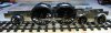
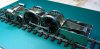
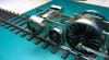
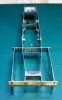
So far i have got the basic chassis built, the leading driver is sprung. I will be using an ABC motor gearbox for it.
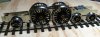
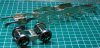
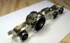
Today I got the cylinders made up
I have yet to provide side control on the front bogie but now I have the cylinders in situ I can work on this .

Its one thing to build it but another to paint it. I am thinking I may need to call in a professional painter
I really want it in GN livery which is not easy
 

Attachments

  • C1 Assembled bogie.JPG
    C1 Assembled bogie.JPG
    234.6 KB · Views: 58
  • C1 chassis with coupling rods.JPG
    C1 chassis with coupling rods.JPG
    153.5 KB · Views: 53
  • C1 chassis with cylinders.JPG
    C1 chassis with cylinders.JPG
    201.8 KB · Views: 56
  • C1 chassis with wheels.JPG
    C1 chassis with wheels.JPG
    157.3 KB · Views: 54
  • C1 cylinders.JPG
    C1 cylinders.JPG
    190.6 KB · Views: 54
  • C1 Frames and bogie.JPG
    C1 Frames and bogie.JPG
    224.7 KB · Views: 51
  • C1 frames laid out for assembly.jpg.JPG
    C1 frames laid out for assembly.jpg.JPG
    185.9 KB · Views: 52
  • C1 mainframes and pony.JPG
    C1 mainframes and pony.JPG
    193.4 KB · Views: 54
  • Frames and rear axle frames 3.JPG
    Frames and rear axle frames 3.JPG
    98.3 KB · Views: 51

oldravendale

Western Thunderer
Frankly I reckon you've done remarkably well to get this far so quickly!

I'm interested in the response you received from William to your enquiries. Also, what references are you using? Do you have drawings because I'd be very cautious about assuming that you can rely on any of the kit dimensions. Or is this kit one of those bought in by William in which case it may actually be perfectly sound!

Brian
 

topshed34a

Western Thunderer
Frankly I reckon you've done remarkably well to get this far so quickly!

I'm interested in the response you received from William to your enquiries. Also, what references are you using? Do you have drawings because I'd be very cautious about assuming that you can rely on any of the kit dimensions. Or is this kit one of those bought in by William in which case it may actually be perfectly sound!

Brian
Hello Brian
William has been very helpful, he knows that there have been comments on the 7mm egroup about it and so I would assume it would be in his interest to help me as I will probably submit an article to the gazette. Would I buy one again? well if you want a C1 and your not a scratch build wiz then really you have no choice. A few people who are professionals and one in particular who is very well known said he wouldn't touch an ACE kit due to the fact that you need to fight the kit. As for me I am a simple hack, with basic skills and the optimism that if I buy a kit and applying reasonable intelligence I should be able to build it
The instructions are basically no good and when you consider it what you don't want is reams of text, what you want from an engineering point of view is drawings with pertinent notes.
I think that to write instructions I would have to build several of the same kit because like all things your realize as you go that you could have done things in a different order or manner.

I think the problem for kit builders is when people review it the person may be a complete twit with no skills what so ever and there in lays the problem I feel.

When ever I build something I come across a problem and I normally think, well it must be me, I must be completely stupid, I must be the only one having problems.
Many have said good luck, we wish you well you poor mug, and I get the point, but I think now I am determined that I am going to defy everyone and build it as a personal challenge.
Like most things never be afraid to call for help.
Even If I build a reasonable model in the raw I then have the biggest challenge of the lot, painting and lining. Painting is ok but lining is where you need people like Steve Barnfield or Ian Rathbone. Even transfers can be hard to get to look good.
The kit comes with some really silly things like an etched brass back head, but now you can get a cast one. Also the cross heads are white metal and I am going to discard them for lost was jobs from laurie Griffin.

If all else fails I consult ruby dog who like to sit on my shoulders LOL
 

Steph Dale

Western Thunderer
He he, I like it; self-discovery through the medium of etched brass.
It's probably marginally safer than yoga.
Steph
 

topshed34a

Western Thunderer
He he, I like it; self-discovery through the medium of etched brass.
It's probably marginally safer than yoga.
Steph
Steph, hopefully I will get through it and make a reasonable model.
I think sometime I simply want a no brainer, something I can enjoybuilding instead of thinking WTF.

The connoissuer J50 was such a kit, simple and just follow the diagrams.
I have 3 Finney kits and im told they all go together well.

The problem I face now is that the laminated coupling rods and connecting rods are 3mm think but the slaters bushes are only 2.5 mm thick.

Steve Rowe
 

topshed34a

Western Thunderer
Well today Im at the stage that I can complete the chassis although I have decided now to work on the body to ensure that said body and chassis have a blissful marriage.

The problem is that the footplate has to be bent up over the drivers and down under the firebox. Any attempt to cut the valence from the fret and then bend the footplate I feel will be a disaster. When I built the Fourtrack J6 which is the same kit as the London Road Models kit but has been scaled up it had a neat fold up system to make a box like a C channel and then the footplate was soldered to the valences and the basic body was built before cutting away and filing the underside of the valences . My photo shows the etches.
I think what I am going to attempt is to solder the valence etches at perpendicular to a sheet of brass and the same parralel width ad the footplate then solder the footplate to the valences, I will need to complete the basic body to add sufficient strength to the footplate before I cut way the valences from the etch.

Having said that any one else can think of an better way then let me know as I like the simple approachC1 foot plate and valence etch.JPG
 

Rob Pulham

Western Thunderer
Hi Steve,
I am following this with interest because I will be following in your footsteps at some point. I will have the extra challenge of lengthening the frames on mine to add to the fun.
 

adrian

Flying Squad
I think what I am going to attempt is to solder the valence etches at perpendicular to a sheet of brass and the same parralel width ad the footplate then solder the footplate to the valences, I will need to complete the basic body to add sufficient strength to the footplate before I cut way the valences from the etch.

Having said that any one else can think of an better way then let me know as I like the simple approach
If I follow you correctly - I think what you are suggesting is what the kit designer had in mind. Leave the valences attached to the etch with the coupling hooks and steps but remove it from the outer frame - i.e. the bit with the writing GNR Atlantic 4-4-2 written on it. The two sides should be symmetric because they have obviously reversed the film for the other side with the writing in reverse. Solder in some spacers to make up the C channel for building up the footplate , splashers etc.

If I was scratch building the loco then I think I'd make up a wooden buck from hardwood to support the footplate at the correct levels front to rear. This gives you something to rest the footplate on when soldering on the splashers, firebox etc. You should try scratch building at some point - to be perfectly honest I find it easier than kit building. These days with all the excellent castings available I think scratch building the platework and buying the castings in is probably easier than kit building sometimes!
 

topshed34a

Western Thunderer
Hi Steve,
I am following this with interest because I will be following in your footsteps at some point. I will have the extra challenge of lengthening the frames on mine to add to the fun.
Bob your way to ambitious for me, I just want something that looks the part even if it isnt 100% correct.
Im glad it is of some value to you, as the instructions are not good.
William from ACE is very helpful and to be honest if I were designing a kit I think Iwould need to build a few before I got the instructions correct.
I would take the approach that apart from a few skills the purchase knows nothing .
Stay tuned and if you got any ideas dont hold back, sometimes thinking outside my own square is hard
 

topshed34a

Western Thunderer
If I follow you correctly - I think what you are suggesting is what the kit designer had in mind. Leave the valences attached to the etch with the coupling hooks and steps but remove it from the outer frame - i.e. the bit with the writing GNR Atlantic 4-4-2 written on it. The two sides should be symmetric because they have obviously reversed the film for the other side with the writing in reverse. Solder in some spacers to make up the C channel for building up the footplate , splashers etc.

If I was scratch building the loco then I think I'd make up a wooden buck from hardwood to support the footplate at the correct levels front to rear. This gives you something to rest the footplate on when soldering on the splashers, firebox etc. You should try scratch building at some point - to be perfectly honest I find it easier than kit building. These days with all the excellent castings available I think scratch building the platework and buying the castings in is probably easier than kit building sometimes!
Well at least were on the same page
 

topshed34a

Western Thunderer
If I follow you correctly - I think what you are suggesting is what the kit designer had in mind. Leave the valences attached to the etch with the coupling hooks and steps but remove it from the outer frame - i.e. the bit with the writing GNR Atlantic 4-4-2 written on it. The two sides should be symmetric because they have obviously reversed the film for the other side with the writing in reverse. Solder in some spacers to make up the C channel for building up the footplate , splashers etc.

If I was scratch building the loco then I think I'd make up a wooden buck from hardwood to support the footplate at the correct levels front to rear. This gives you something to rest the footplate on when soldering on the splashers, firebox etc. You should try scratch building at some point - to be perfectly honest I find it easier than kit building. These days with all the excellent castings available I think scratch building the platework and buying the castings in is probably easier than kit building sometimes!
Well its good we are on the same page, I got an email from ace confirming the jig approach.
With the fourtrack J6 the jig was built into the etch and you simply foldeded up the etch at the sides.
This is more time consuming bur as long as I get the valences accurate and square it should be ok.
 

topshed34a

Western Thunderer
Ok so I have cut out the valence etch and also the footplate, just like Baldrick, I have a cunning plan.
I have a sheet of brass and the insides of the valences should be 54mm apart so I thought I will solder the valence etches to the brass 54mm apart and hopefully parallel and perpendicular, I will then cut the middle of the brass sheet leaving just a few stretchers at the end and say in the middle, I can then solder the footplate to the valences then build the smokebox boiler and cab before cutting the body away from my extremely cunning home made jig. What do you think, will it work or is my plan less than cunning?????

I asked Ruby dog and she thinks everything I do is really good LOLC1 footplate and valence layout.JPG
 

topshed34a

Western Thunderer
Very busy this afternoon, Ruby dog is great for discussing technical issues with also chewing bones and playing chase the ball that goes on for hours
But this is time to ponder my next move.
So I made up the jig and cut out the middle of it with a dremel so I can solder the valence to the footplate from inside.
I used electrical solder which is really hard to do as the sheet of brass saps the heat away but no matter the jig is only temporary anyway.
As you can see I am now ready to solder the footplate to the valence, but before doing this I wll solder the front buffer beam on and ensure the valences is hard up again the buffer beam.
Hopefully within a few days I will have what looks like an Ivatt C1

Note how I have cut two apertures in the jig and left a piece in the middle just for mechanical strength.C1 footplate jig.JPG
 

topshed34a

Western Thunderer
Steve

That looks good and should work.

Now just carefully bend the footplate to match the valence.

Richard
Thanks Richard, the good thing is where it bends up and down is half etched so it will bend easy, ie no need to anneal it
Hopefully by the time you get back to London I will have something approach a loco.
Thanks for dropping in the kit, and it was good to have a few pints wasn't it
 

topshed34a

Western Thunderer
Well the jig worked,
Here is the footplate soldered on the jig

I just had a thought regarding the front bogie

At present it is attached to a frame spacer using a swing link. I can use a slotted spacer and then mount it on a bolt with some side control, however this means I can attach the body to the nut which will be soldered on the footplate under the smokebox saddle

If I were to solder a nut a bolt or a nut under the footplate but ahead of the smoke box, I could then add another spacer over the front wheel and then use a bolt to attach the body.

Ivatt C1 footplate.JPG
 

topshed34a

Western Thunderer
Looking great Steve, and very rapid progress!

Hoping to build a C1 myself eventually, loco 3279 which was briefly built as a 4 cyl engine with K2 outside cylinders

LNER 4-4-2 No. 3279 - Photos - Our collection - National Railway Museum

A good looking engine!

JB.
JB2 No doubt you will design your own completer with working reverser.
JB1 said your a dtails man right down to the cast whitemetal sandwiches for the crew. LOL.

I have parts in this kit that I have no idea what they are?

I think a lot of emails tp William Ascough are needed.

I think the downfall of many kits is lack of good documented instructional drawings.

I think the best approach to designing a kit and writing instructions is to assume that the person knows nothing and needs to be taught.
I am now going to build the body so I can cut away the jig

Stay in touch Jonathon
 

topshed34a

Western Thunderer
The cab has now been folded up. I annealed the sides just above the window cutout so I could bend it. I bent it over a drill bit whilst the sides were clamped in a vice. I have added the front beading using 188 solder , but the cab was electrical solder.
I have to add the rear beading which is in 5 pieces.


Pretty pleased with the results so far.

C1 cab sat on footplate.JPG C1 Cab with front beading.JPG
 
Top