Locomodels
Western Thunderer
This will be, hopefully, a straight forward build, once the modifications for conversion to S7 are taken care of. It will not be a blow-by-blow account of the entire build, it is only the changes needed or problems encountered in building it in S7 that will feature here.
So off we go. The crank axle is already made as you know, turning the wheels to suit, making new frame spacers and modifying other parts to fit the wider frames are all that is required, he says optimistically.
The wheels will be done soon, these are straight forward and need not trouble us here.
Therefore making new, wider, spacers is the first job to tackle. Making the crank axle was just a time filler whilst I thought about this over the last couple of weeks. The conclusion that I came to was, I believe, the simplest method of achieving this.
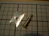
Basically it was to cut a strip of 0.028” n/s to the required width, which in this case was 29mm. and then copy the existing narrow gauge spacers onto the wider strip. My simple method of doing this was to cut a piece of the strip to the required length, matching the existing item. Clamp the narrow piece to the wider piece, lining them up along one side. And then file the edge copying the position of the tabs. I should, of course, have mentioned that David Andrews uses the slot and tab method of part location.
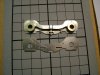
I clamped the pieces together with a toolmakers type clamp, held the parts in the vice, using aluminium vice jaws and proceeded to file the edge to match. This is surprisingly easy as it only takes relatively few file strokes to achieve this as we only have to remove 28 thou. I used a ‘safe edge’ file to stop cutting into the tabs. As I filed I watched for the file to just touch the cusp of the etched part that I was copying. Repeat this on the other side and then de-burr the new part. See picture below ( I hope).

View attachment 16958
Some of the parts had holes in them, and etched positions for nuts which I will not be replicating, plus fold lines.
To get the holes in the correct position I scribed a centre line on the new part and clamped the pattern centrally over it. Scribed round the holes and marked the position of the fold lines, if any. Centre spotted for the holes, using my invaluable and old ‘Optical Centre Punch’ which I must have had for around forty years. If you don’t have one of these I respectfully suggest that you get one, you will never ever regret it. It is one of those tools, when you have one, that you can’t understand how you ever managed without it.


The fold lines are something else and I have made a couple of tools for it. These I have also had for some time. They cannot be bought so you have to make them yourself. The larger one was made from 1/2” x 1/8” gauge plate, filed up hardened, tempered and honed with a stone. The small one is Silver Steel rod, heated and hammered to shape, filed and again hardened and tempered and honed. This might seem like a lot of work, but it is surprisingly easy and the tools will last you a lifetime.

Alternatively you can scribe deeply and file the fold lines with Swiss needle files, triangular and square do a good job. If you have a milling machine you could also mill them with a tiny, say 1.5mm dia ball nosed cutter.
One of the new spacers in the picture has been cut with my home made gravers. I used the mill for the others.
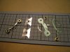
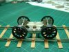
In the following picture you can see, on the left, the new wider spacers that I have made. These are next to the original narrower ones. The items on the right are all the pieces that will need modification to fit the new wider frames.
These are the cylinders, the motion plates, both inside and outside, and some footplate brackets. Apart from the brass cylinder plate all the others are laminated from two 0.028” thick etchings.

So all the required new S7 frame spacers are now made. Total time, including cutting all the parts from the frets, filing away the tabs, and cleaning up the edges was around 8 hours. Not all at once but spread over two days.
Well that is the present state of play.
My next job will be to assemble all the parts to the frames and fit the axles. This will be bog standard procedure.
The next ‘interesting’ episode will be fitting the cylinders, motion brackets and slide bars. See you then.


 whilst my Sons have been saying for years that they are glad that I have not
  .
.