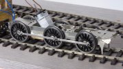
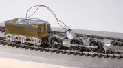
The Heybridge Railway, 1889 to 1913

Richard Gawler

Western Thunderer
Hanging on the fence, an entire train makes a noise especially a freight train. It seems odd to have sound effects coming from the loco, nothing from the rest of the train. I have a Rapido APT-E with sound, and the sound effects are more convincing because there are loudspeakers at both ends. But having heard them for a minute or so I just want to turn them off and this is now my only sound-equipped model. It is as though the sounds intrude into my imagination. I know many people really enjoy DCC sound and I don't want to detract from this, but it is not for me. Perhaps a button to sound a steam whistle, but nothing else.
 

simond

Western Thunderer
Fair enough!

In the dim and distance past my 7mm apprenticeship was on Ken Longbottom’s magnificent Diggle, Halebarns & Westport railway. Sounds were supplied by literally dozens of old reel-to-reel tape recorders mounted under the baseboards in Halebarns. An express would shriek as it hurtled through the station. Most evocative!
 

Ressaldar

Western Thunderer
Fair enough!

In the dim and distance past my 7mm apprenticeship was on Ken Longbottom’s magnificent Diggle, Halebarns & Westport railway. Sounds were supplied by literally dozens of old reel-to-reel tape recorders mounted under the baseboards in Halebarns. An express would shriek as it hurtled through the station. Most evocative!
Hi Simon,

keep hold of your memories of Diggle, the layout has gone into disrepair over the past few years and is I believe in a very sorry state now. My only visit was over five years ago and not much if anything was running then. A great shame.

regards

Mike
 

Richard Gawler

Western Thunderer
I have an unfinished cameo layout, the opening between the wings is about 1.2 m. I wonder if I could arrange a pair of loudspeakers, one left and one right, behind the wings and projecting sound into the stage area. I ought be able to manage birdsong or the sound of a storm.
 

simond

Western Thunderer
Thanks Mike,

I understand so. It is a massive undertaking for one person to keep up.

Ken was hugely industrious (and cantankerous in roughly equal measure!) and a very skilled modeller, he particularly loved signals and signalling, and the interlocking (and track feeds) were all routed through banks of 50V PO Relays, which also provided the motive power for the signals and points. From memory there were no track feed isolators, so, for example, the ground signal would permit a loco to exit the end of a terminal road.

IIRC, he was an airframe instrumentation “pixie” at RAF Sealand, but we’re talking fifty years ago. He was very kind to Neil (a school friend) and I, Neil’s dad, Gordon, was the instigator of the tape recorders, and was our “in“ to such illustrious company, and it was a priviledge indeed to reach the level of approval which saw two teenagers regularly operating Diggle unsupervised. (Though perhaps the incident with an express double headed with our yard pilot should be brushed over - that’s what the lever collar is for!)

happy memories indeed.
cheers
Simon
 

Richard Gawler

Western Thunderer
I have made a start on the chassis for my Y14 and made some decisions about the model along the way.

I met Big Jim at a model railway show and he told me, nearly all of the times he has to dig people out of holes is after they have tried to add compensation to one of his rigid chassis. I have no plans for pickup-ups on this loco, and the centre axle rides higher than the outer two to discourage fore/aft rocking; and so I am going to give my loco with a rigid chassis. This will keep things as simple as I can for myself.


DSC_1130.jpg
The only design work for me so far is to arrange slots for the wiring.

There will be four wires from tender to loco. Two wires for the motor and two for a firebox LED. This gives me an option to omit the LED and double-up the wires to the motor if it regularly takes more than half an amp or so during normal use.

The new slot in the rear spacer is for the pins on the back of a Molex-style connector. The pins will pass through this slot into a piece of Veroboard on the other side. The connecting wires will then go from the Veroboard to the motor and the LED. I have also cut a slot in the next spacer along, so the wires can pass through there as well.

DSC_1112.jpg
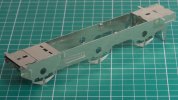
The started my work on the frames by cutting off the supports for the brake rod behind the rear axle. Then I filled the holes for the plunger pickups and the pivots for the brake hangers, I used slivers of brass rod soldered in from behind. I also reamed out the holes for the axle bushes.

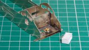
At the moment, one frame is soldered up solid onto the frame spacers and the other frame is still tacked into place in case it has to come off. Hence the gap visible at the corner nearest the camera. I put the wheels and their bushes in for a while and stood the chassis on the track, and there is no rocking across the diagonals.
 
Last edited:

Richard Gawler

Western Thunderer
DSC_1146.jpg
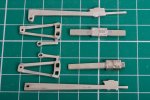
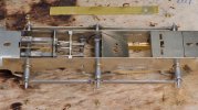
Laminations of nickel silver parts to make the inside motion.

The parts for the connecting rods looked a bit peculiar sitting in the fret and only made sense to me when I put the rods into the chassis and remembered the middle axle (where they would go on the prototype) has got to carry the worm gear.

I am using Carr's 145 solder with phosphoric acid flux. It seems best to do the clean up in hot soapy water - the kitchen limescale removers tend to leave marks on the metal which then has to be scrubbed off with a toothbrush. The camera shows up faults which I did not notice like the slight misalignment of the part centre left but it seems best to post this photo and then take a file to the problem. There is some solder and flux to clean up right centre too.

The motion will end up visible below the boiler, but hopefully the worm gear sitting behind it will not.
 
Last edited:

Richard Gawler

Western Thunderer
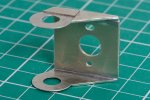
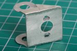
This is my take on the gearbox/motor mount for my Y14. The mount has mounting holes at 12.5 mm pitch for a Mashima 1833 and I want mounting holes at 15 mm pitch for a Canon CN22.

DSC_1151.jpg
I have cut a rectangle of nickel silver sheet, drilled the three holes and sweated this onto the inside of the mount. I have elongated one of the holes to give me some adjustment of the gear mesh, I can make this hole longer if need be.

DSC_1155.jpg
On the outside I have added some shims from scrap fret so the mount is a snug fit between the frames. So it should be straightforward to solder the mount into the chassis. The motor will hide the original mounting holes.

I suspect some larger mounting holes and two M2 washers would be enough, and indeed most of my handiwork will be hidden inside the chassis, but it was a nice little practice piece all the same.
 

Richard Gawler

Western Thunderer
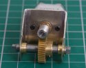
I ended up enlarging the middle hole about 1/4 mm to get a complete range of adjustment. So I can set the motor with the gears on the verge of locking up solid, and backed off a bit to give a good mesh for running.

DSC_1167.jpg

The gears are the same design as the ones I used in Nellie. The worm gear is wide enough to let me have some sideplay on the driven (centre) axle.

The ratio is 40:1. For Nellie, with the speed controller set to its "shunting" profile, this ratio gives me a maximum scale speed of 15 mph. Setting the controller to use its "normal" profile has increased this to about 22 mph. The wheels of the Y14 are about 50% larger than those of Nellie, so I might see a maximum speed of 30 mph. The Y14 has a different motor of course, and the Y14 plus tender will be a lot heavier than Nellie, so I will have to wait and see what I get. If I can have a steady scale 20 mph for a long freight train I will be very happy.
 
Last edited:

Richard Gawler

Western Thunderer
This is my first kit with nickel silver parts so I built the inside motion (which doesn’t need to work) for practice before I tackled the side rods.

DSC_1170.jpg
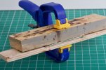
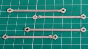
The side rods are laminated together from three layers, plus bosses. My approach to these has been to leave the cusp on the parts and sweat them together. Then clamp them so the edges are accessible and “paint on” solder to fill the undulations between them, and then finish the edges with a file and abrasive paper.

DSC_1171.jpg
I have tinned the outside faces with 100 deg C solder to try to make them look more like steel than nickel silver, thank you to @Rob Pulham for this tip. Finally I soaked them in Cif “Stainless Steel Sink Cleaner”. This contains an ingredient (I have no idea what) which puts a dull sort of a patina on soft solder.

The chassis is rigid but the rods are articulated. I expect I will find out the reason for this as the build goes on. Perhaps it is to allow sideplay on the middle axle without needing overlong crankpin bushes.
 

Richard Gawler

Western Thunderer
I have added the axle bushes and temporarily added the wheels and pushed the chassis to and fro along my test track.

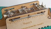
I used the Poppy's builder box for the tender chassis and this came out flat and square, so I felt happy using the box again for the loco chassis. I had to ream out all of the holes in the side rods to fit them over the extended axles. The ends of the extended axles are thinner than the crankpin bushes so I will have to ream out all of these holes again later.
DSC_1176.jpg

DSC_1182.jpg
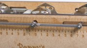
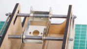
This builder box is a "special", the middle hole is elongated upwards and downwards to take the offset axle. It seems to work.
DSC_1181.jpg
I have set up the bushes on the two outer axles to give me barely 0.2 mm side play (29 mm over faces), and the bushes on the centre axle to give me as much side play as I can have, about 1.2 mm (28 mm over faces).

I soldered the centre bushes onto the motor mount not the frames, so I can rotate the mount to find the angle where the motor will fit inside the body after I have built it.
DSC_1184.jpg
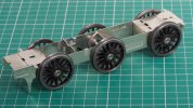
Finally I put the wheels in for a brief trial. A Slater's axle is thicker than the extended axles (about 0.001 inch more) so I had to ream out the bushes to let me put the wheels in.

The chassis can negotiate a Setrack curve (1,020 mm radius). The chassis can also negotiate a Setrack point, but the flanges of the centre wheels tend to kiss against the insides of the rail heads - this is because the nominal 32 mm gauge narrows a bit through the curved point blade.

This ability rather exceeds expectation. I don't have a "thing" about very tight curves but this is this almost certainly the largest loco I will want to run on my layout; and so if this loco runs through a Setrack point then I can incorporate this point into my fiddle yard and dispense with having a separate test track.

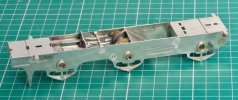
Above all, the chassis runs freely and sits flat on the track and does not rock across its diagonals . . . I am very pleased with this.
 
Last edited:

Richard Gawler

Western Thunderer
DSC_1245.jpg
I spent a full three hours putting the internal motion and valve gear into place. This is the first place in the kit where I couldn't persuade the parts to fit as intended.

DSC_1249.jpg
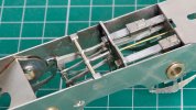
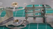
There is a length of brass wire holding the valve gear and the truncated ends of the connecting rods, and this wire formed itself into a pronounced curve when fitted through these parts and the etched holes in the frames.

My solution is to enlarge the holes in the frames so the two ends of the wire can move forwards, and attach the ends to two scraps of fret soldered onto the insides. The work will be pretty much hidden on the outside by the wheels and on the inside by paint.

Three modellers have told me I will have no problems putting this kit together, but as hard as I tried I could not see a way to install the valve gear etches further towards the back of the model - their location is pretty much fixed by the brass rod across the top. Still, this is my first attempt at a loco kit with this level of detail so it may well be the kit is correct and I have failed to make an adjustment somewhere else.

DSC_1251 (1).jpg
I am now stuck for parts. Back in the Summer when I bought the kit I had the presence of mind to buy some 10BA taps so I could try 10BA crankpins instead of the Slater's 8BA ones. I did not however order up the screws, nuts and washers to suit . . . these are now somewhere in the postal system.
 

Richard Gawler

Western Thunderer
DSC_1263.jpg
I bought a set of "hornblock alignment axles" (amongst other goodies) from Premier Components at the Guildford Trade Show last Saturday. I did not know such things had been invented . . . they will be good for a chassis with compensation, a little less useful for a rigid chassis but with all four side rods slid home onto the axles and all four rods parallel to the chassis, it looks like the holes in the rods ought to line up with the crank pins. The strip of brass with a hole in it is my "consumable tool" for filing down the crankpin bushes to length to suit the bosses in the rods.

DSC_1288.jpg
The crankpins are 10BA screws, these finally arrived today. I have left them overlength so I can add lock nuts and be able to dismantle everything for painting. I tapped the wheel bosses 10 BA to suit, I think this helps the screws to go in square. The bushes are the Slater's ones, tapped 10BA and threaded onto the screws. If I go back to using 12BA screws (as supplied with the Slater's wheels) I will try to tap the holes in the bosses first and not rely on the screws to cut their own threads.

DSC_1287.jpg
And this contraption has shuttled up and down my test track. Time for a beer :)
 

Dog Star

Western Thunderer
If I go back to using 12BA screws (as supplied with the Slater's wheels) I will try to tap the holes in the bosses first and not rely on the screws to cut their own threads.
Or consider the Slater's S7 wheels available from the S7 Group - these items have a tapped metal bush for the crank pin, those bushes are moulded into the wheel boss. OK - you may not find an appropriate wheel in the current range and you have to exchange the S7 axles for the FS equivalent....
 

Richard Gawler

Western Thunderer
There is food for thought here.

I want my Y14 to be my "universal" loco I can take to run on friend's layouts as well as my own. I want it to cope with the club layout (Peco points with large flangeways), a garden railway also with Peco points, a garden railway with three-rail coarse scale track but only one point and a garden railway basically FS but stud contact. Also another club layout built I think to ordinary 0-F standards.

I have pretty much decided on 0-MF trackwork for my own layout when it happens. I will build all the track by hand because I want pre-grouping sleepers and timbers so I might as well build something which will run well. I expect the Y14 will be ok on this as well as on all these other layouts but I could try some S7 wheels on a future model. They do look good! Supposing my next loco is the Slaters MW F class, perhaps I should start by finding someone to turn the tyres down to the S7 profile? These wheels are a 1/8 inch axle so swapping axles sounds good but not for this particular loco.
 
Last edited:

Richard Gawler

Western Thunderer
Send @Eastsidepilot of this parish an email or PM. He turns mine for me.
Dave
Dave, I like the sound of this but I need a slower start. I can begin by asking the broad gauge folk (if this is the proper term) at the club whether they have tried S7 wheels on 32mm gauge axles on the club track. Even a small wagon would be a very good test of what is doable because this track has been dismantled and re-erected many hundreds of times over its 30 years. Then decide what the way ahead for my F class. I do want to keep interoperability with other people's tracks because my own layout is going to be maybe 11 feet long and I want to watch my trains running for longer periods from time to time.
 

Richard Gawler

Western Thunderer
In spite of my best efforts the chassis still had a pronounced squeak on every revolution of the wheels. This came from one crank pin (rear left) - I had already opened up the hole in the side rod here but obviously not enough. So the tiniest amount of work with a five-sided broach, maybe half a thou added to the diameter of the hole, has pretty much removed the squeak. This means, I have ended up enlarging the hole in one boss by about 2 or 3 thou in all. The other five bosses are still untouched. I don't know whether this is typical or if I need to find a better way to set up axle bushes and crank pins. I think I can be a perfectionist at times but a non-modelling friend suggests more likely all the time.
 

simond

Western Thunderer
Whilst S7 wheels will look nice in their own regard, I’m not sure what is to be gained by using them on 32 or 31.5 track.

Without doing the sums, I expect that using S7 wheels (set to 0F BTB) on 31.5 track would be much like using 0F wheels on 32mm track, a compromise that leads to adequate but not smooth running. And using S7 wheels on coarse scale track is likely to lead to derailments unless the loco chassis is particularly compliant, and speeds are obviously slow. And the dimension that “matters” is the check gauge, or BTF.

There are three standards, S7, 0F and 0C, which are not interoperable. 0MF, which I have used for my track, is a subset of 0F, using 0F wheel standards, which seems to me to give the best compromise of running, and interoperability. It is possible to build universal points which will accept 0C and 0F, and they were popular in garden railways some years back, but i helped convert one large railway to Peco because they were more trouble than they were worth for the one or two visiting locos with coarse standard wheels.

My approach and recommendation is to build your locos & stock to 0F standards, and your track to 0MF.

Lots more more info on the Templot forum.

hth
Simon
 
Top